A double-layer crucible core melt collection device with internal cooling pipes

A core molten material and double-layer crucible technology, applied in cooling devices, emergency protection devices, reactors, etc., can solve the problems of failure of the lower head of the reactor pressure vessel, melting of fuel elements, and damage to the integrity of the containment vessel. Improve retention success rate and cooling efficiency, improve reliability, and enhance overall cooling efficiency

Active Publication Date: 2022-01-18
CHINA NUCLEAR POWER ENG CO LTD
View PDF29 Cites 0 Cited by
  • Summary
  • Abstract
  • Description
  • Claims
  • Application Information

AI Technical Summary

Problems solved by technology

[0003] When a serious accident occurs in a pressurized water reactor nuclear power plant, the loss of core waste heat removal means will evaporate and exhaust the coolant, the core will be exposed and continue to heat up, the fuel elements will melt due to the loss of cooling, and the core melt will fall into the reactor pressure vessel (RPV) lower chamber, which in turn causes the failure of the lower head of the reactor pressure vessel. If effective measures cannot be taken to cool it, the core melt may melt through the pressure vessel
After the pressure vessel melts through, the core melt is sprayed directly onto the containment raft foundation to interact with structural concrete (MCCI), and gradually erodes the containment raft foundation downward at a relatively fast speed within a certain period of time. If the thickness of the raft foundation is insufficient , the bottom plate may be melted through and cause the integrity of the containment to be destroyed
The radioactive material will then go directly into the soil, causing serious environmental impacts

Method used


Image

  • A double-layer crucible core melt collection device with internal cooling pipes
  • A double-layer crucible core melt collection device with internal cooling pipes

Examples


Embodiment Construction

[0037] The specific implementation manners of the present invention will be further described below in conjunction with the accompanying drawings.

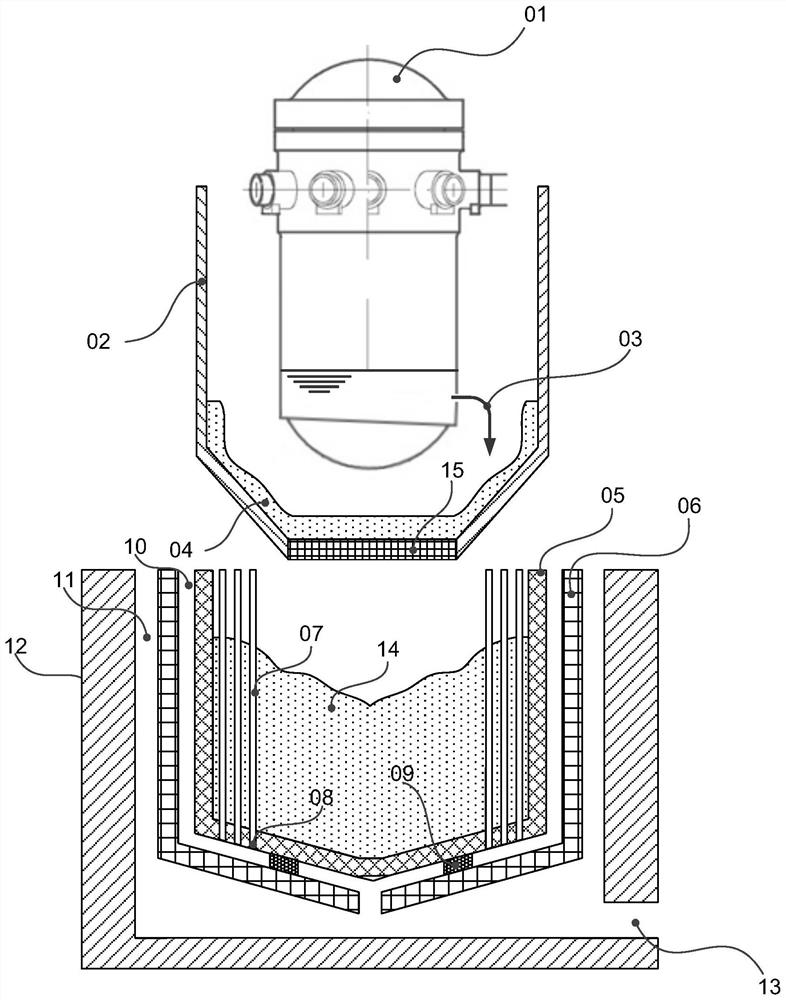
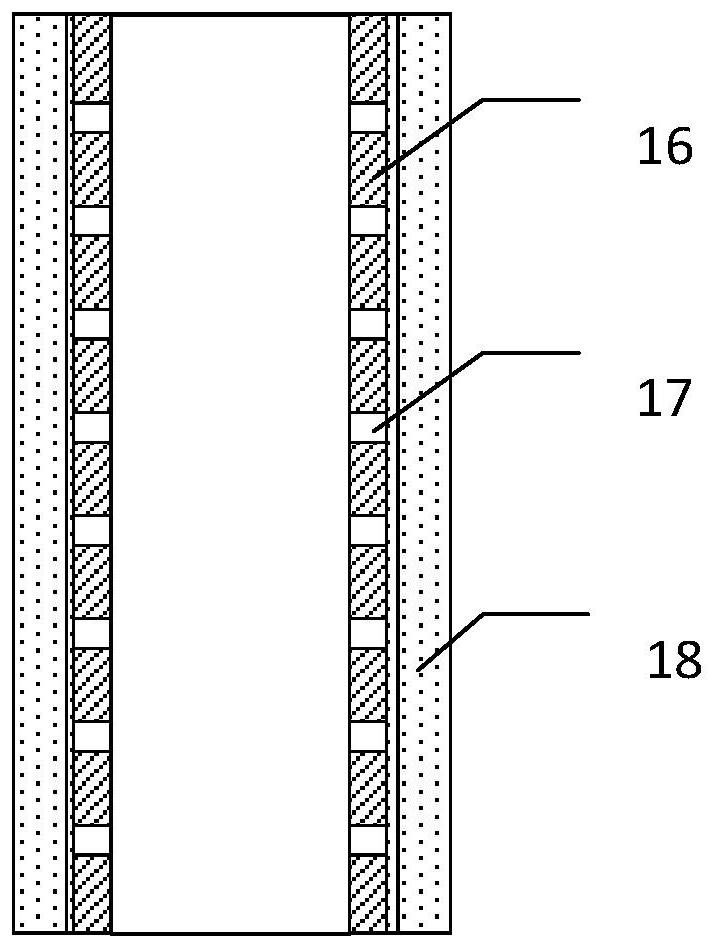
[0038] The composition structure of an exemplary double-layer crucible core melt trapping device with internal cooling pipes of the present invention is as follows: figure 1 As shown, it includes reactor pressure vessel 1, high temperature resistant drainage protection layer 2, path 3 for core molten material sprayed out from the pressure vessel after the accident, special concrete 4, inner crucible 5, outer crucible 6, cooling pipe 7, cooling Pipe water inlet 8, support base 9, cooling flow channel 10, stack pit cavity 11, stack pit 12, cooling water injection port 13, sacrificial material stack 14, fusible metal grid plate 15.

[0039] The inner crucible 5 is arranged directly below the reactor pressure vessel 1, and it is fixed in the outer crucible 6 located outside the reactor pressure vessel 1 below the reactor pressure vess...


PUM


Abstract

The invention belongs to the technical field of nuclear safety control, and relates to a double-layer crucible core melt collecting device with internal cooling pipes. The trapping device includes a reactor pressure vessel, an inner crucible, an outer crucible, a cooling flow channel, a pile pit, a pile cavity, a cooling pipe, and a water inlet of the cooling pipe. The inner crucible is arranged directly below the reactor pressure vessel, and is fixed In the outer crucible outside and below the reactor pressure vessel, a cooling flow channel for cooling water flow is formed between the inner crucible and the outer crucible, and the outer crucible is installed in the pile pit cavity formed inside the pile pit; the inner crucible There are multiple cooling pipes inside, and each cooling pipe communicates with the cooling flow channel through the cooling pipe water inlet at the bottom. There are small holes on the side walls of some cooling pipes and the outside is covered with a 5-30mm thick sacrificial concrete protective layer . Utilizing the trapping device of the invention can remarkably improve the retention success rate and cooling efficiency of the core trap for the core melt.

Description

technical field [0001] The invention belongs to the technical field of nuclear safety control, and relates to a double-layer crucible core melt collecting device with internal cooling pipes. Background technique [0002] After the serious accidents at the Three Mile Island and Chernobyl nuclear power plants, the nuclear power industry began to focus on research and research on the prevention and mitigation of severe accidents. Due to engineering and other requirements. [0003] When a serious accident occurs in a pressurized water reactor nuclear power plant, the loss of core waste heat removal means will evaporate and exhaust the coolant, the core will be exposed and continue to heat up, the fuel elements will melt due to the loss of cooling, and the core melt will fall into the reactor pressure vessel (RPV) lower chamber, which in turn causes the failure of the lower head of the reactor pressure vessel. If effective measures cannot be taken to cool it, the core melt may m...

Claims


Application Information

Patent Timeline
Patent Type & Authority Patents(China)
IPC IPC(8): G21C9/016G21C13/10G21C15/18
CPCG21C9/016G21C13/10G21C15/18Y02E30/30
Inventor 马卫民元一单郭强李炜张丽朱晨韩旭邢继荆春宁堵树宏
Owner CHINA NUCLEAR POWER ENG CO LTD
Why Eureka
Try Eureka