
Pneumatic guide device for lifting of reactor internals as well as assembling use method thereof

A technology of guiding devices and internal components, applied in the direction of reactor fuel elements, reactors, reducing greenhouse gases, etc., can solve the problems of insufficient length, increase the time of the main line, manpower and material resources, and cannot be hoisted by the top cover of the pressure vessel, so as to reduce radiation exposure The effect of reducing the dose, shortening the hoisting period, and simplifying the maintenance workflow

Pending Publication Date: 2019-11-15
CNNC FUJIAN FUQING NUCLEAR POWER
View PDF0 Cites 0 Cited by
  • Summary
  • Abstract
  • Description
  • Claims
  • Application Information

AI Technical Summary

Problems solved by technology

[0003] The long guide column cannot be used for the hoisting of the pressure vessel roof due to interference with the lower end surface of the roof triangle spreader support ring; the short guide column cannot avoid all collision risk points during the hoisting process of the lower reactor internals due to the short guide column , can not guarantee the safety of the hoisting work of the lower reactor internals; therefore, the upper reactor internals can be hoisted by long guide columns or short guide columns, the lower reactor internals can only be hoisted by long guide columns, and the reactor roof assembly can only be hoisted by short guide columns. guide column crane
The hoisting of reactor pressure vessel top cover components and reactor internal components is the main line of the ten-year overhaul of the unit, and the back and forth replacement of long and short guide columns has virtually increased the time and manpower and material resources of the main line.

Method used


Image

  • Pneumatic guide device for lifting of reactor internals as well as assembling use method thereof
  • Pneumatic guide device for lifting of reactor internals as well as assembling use method thereof
  • Pneumatic guide device for lifting of reactor internals as well as assembling use method thereof

Examples


Embodiment Construction

[0044] A pneumatic guiding device for hoisting internal components of a reactor pressure vessel, such as figure 1 As shown, it includes fixing screw 1, which is located on the top of the device and is used to connect the telescopic head 2 and the piston rod 4;

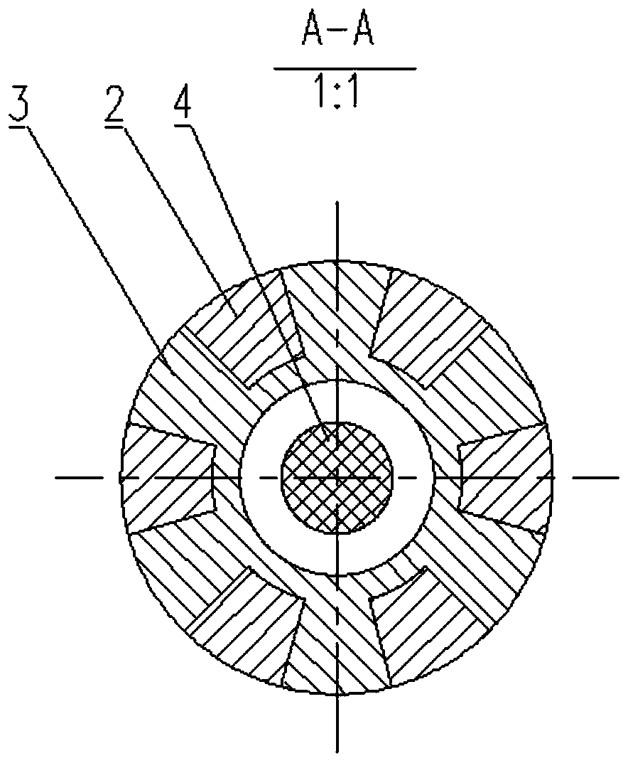
[0045] The telescopic head 2 is placed outside the fixed column 3 of the telescopic head, and the telescopic head 2 slides radially with the fixed column 3 of the telescopic head under the action of the piston rod 4. The cross-section of the mating surface is as follows: figure 2 shown;

[0046] The bottom of the telescopic head fixing column 3 is welded to the top of the cylinder 10, and the bottom of the cylinder 10 is welded to the top of the guide rod seat 6;

[0047] The lower part of the piston rod 4 is welded to the piston 5, and the piston 5 is placed inside the cylinder 10;

[0048] The upper part of the intake pipe 7 is welded with the cylinder air inlet 14 of the guide rod seat 6, and the lower part of th...


PUM


Abstract

The invention relates to a pneumatic guide device for lifting of reactor internals as well as an assembling use method thereof. Through design of a new guide column of which the length can be freely stretched out and drawn back, mutual noninterference among the guide device, a triangular lifting appliance and the reactor internals is realized under three working conditions of lifting upper part reactor internals, lower part reactor internals and a reactor pressure container top cover. Use of the novel guide device of which the length can be freely stretched out and drawn back is particularly important for shortening a ten-year heavy repair main construction period, increasing the economic benefits of nuclear power and reducing the radiation dosage of workers. Lifting appliance transportation and repeated lifting-out and lifting-in in the change process of the guide columns with different length under different working conditions are avoided, the maintenance workflow is simplified, thecover opening and closing lifting work period of the reactor pressure container is shortened and the irradiation dosage of staff is reduced.

Description

technical field [0001] The invention belongs to the field of mechanical maintenance, and in particular relates to a pneumatic guiding device for hoisting the top cover of a reactor pressure vessel and reactor internal components. Background technique [0002] The hoisting work of the top cover of the reactor pressure vessel and the reactor internals is the main line of work for the overhaul of the nuclear power plant. In order to ensure that the large-scale hoisting process can effectively avoid the contact of each easy-to-touch point and cause damage to the equipment, guide columns of two lengths are currently configured in the core overhaul. , used for hoisting upper reactor internals, lower reactor internals, reactor pressure vessel top cover assembly. [0003] The long guide column cannot be used for the hoisting of the pressure vessel roof due to interference with the lower end surface of the roof triangle spreader support ring; the short guide column cannot avoid all c...

Claims


Application Information

Patent Timeline
Patent Type & Authority Applications(China)
IPC IPC(8): G21C19/10G21C19/12
CPCG21C19/10G21C19/12Y02E30/30
Inventor 董波江浩仁许国辉郑东佳洪均郑嘉榕杜鹏程刘星费冬冬苏恒杜召瑞杨全超安峰李振王洪凯肖冰山阮彬标李华金凯何明圆杨凯高原赵贺戴贤源张融
Owner CNNC FUJIAN FUQING NUCLEAR POWER
Learn More