Translucent electrode based on metal nanocomposite structure

A semi-transparent electrode and composite structure technology, applied in the field of optoelectronics, can solve the problems of lower transmittance, etc., and achieve the effect of improving charge injection ability, enhancing electric field, and better effect

Active Publication Date: 2019-11-15
NANJING UNIV OF POSTS & TELECOMM
View PDF5 Cites 0 Cited by
  • Summary
  • Abstract
  • Description
  • Claims
  • Application Information

AI Technical Summary

Problems solved by technology

If the conductivity is increased by increasing the density of the metal nanowire network, its transmittance will decrease

Method used


Image

  • Translucent electrode based on metal nanocomposite structure
  • Translucent electrode based on metal nanocomposite structure
  • Translucent electrode based on metal nanocomposite structure

Examples


Embodiment 1

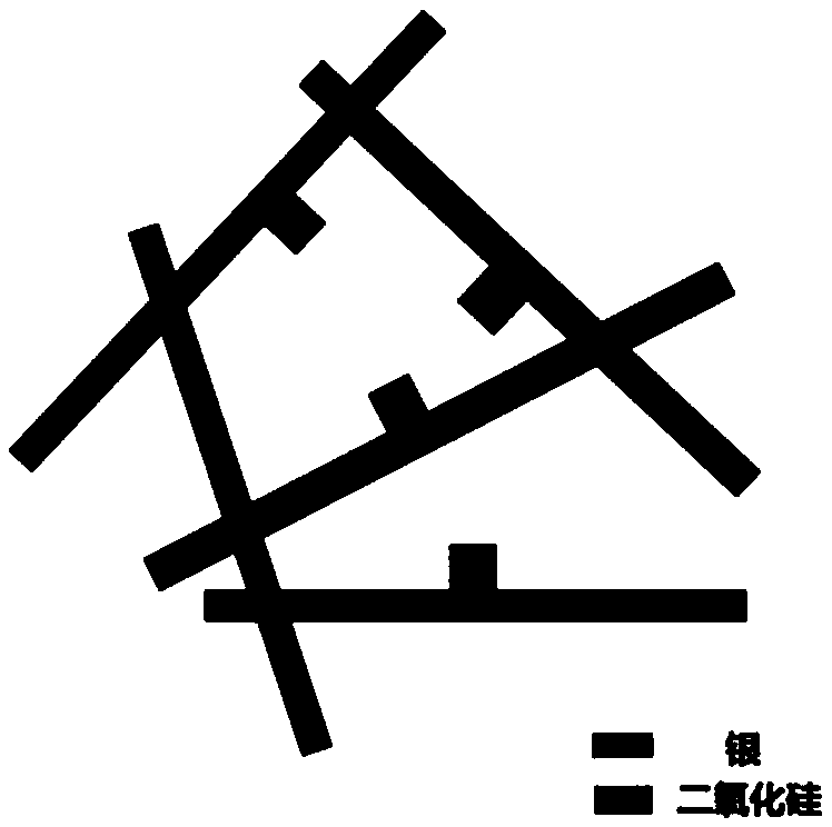
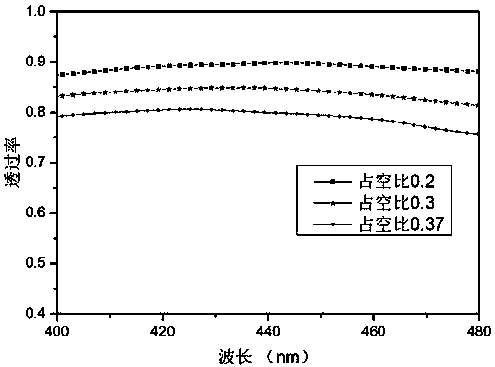
[0030] Use silver nanowires with a length of 1µm and a diameter of 30nm to form a silver nanowire electrode network, and change the duty cycle of the nanowires in the electrode network; figure 2 is the change of the silver nanowire electrode network transmittance with the duty cycle in the 400-480nm band; it can be seen that the silver nanowire electrode network transmittance increases with the decrease of the duty cycle, and the duty cycle is less than At 30%, the electrode transmittance can be basically guaranteed to be above 80%. Since the duty cycle should not be too small, the duty cycle is selected within the range of 20%-30%.

Embodiment 2

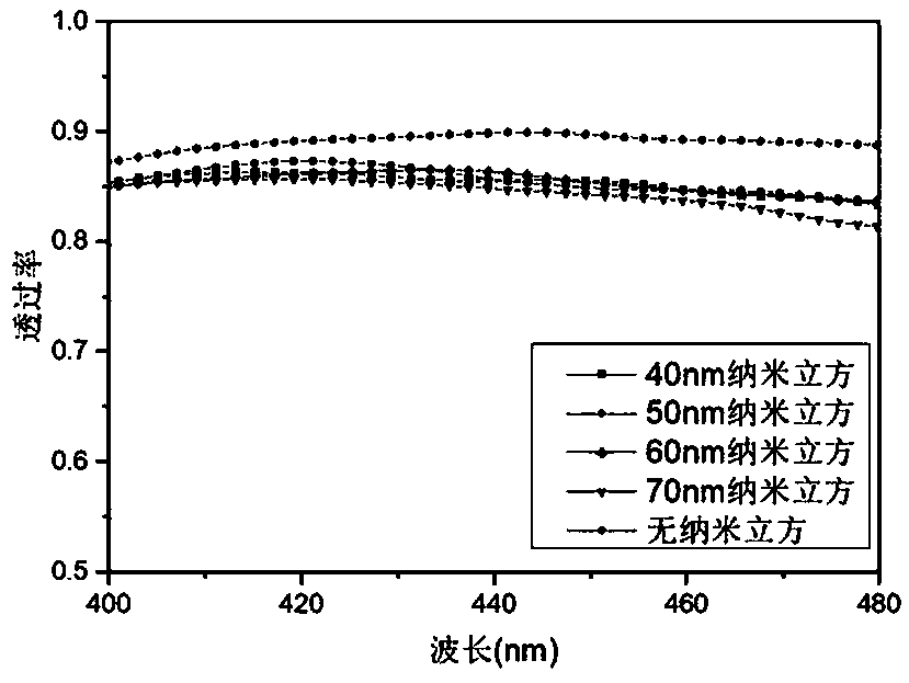
[0032] The silver nanowire electrode network with a duty ratio of 22% is added to the silver nanocube, the silver nanowire length is 1.2 µm, the diameter is 50nm, the distance between the silver nanowire and the silver nanocube is 5nm, and the silver nanocube in the electrode The coverage rate is 0.55%. image 3 In order to change the particle size of silver nanocubes, the change of silver electrode transmittance in the 400-480nm band, it can be seen that the electrode light transmittance is still above 80% after adding nanoparticles. Depend on Figure 4 It can be seen that the electric field of the silver electrode is enhanced after adding nanocubes. Nanocubes with a particle size smaller than the diameter of the nanowire have a weaker effect on enhancing the electric field; nanocubes with a particle size of 50nm and 60nm have a better effect on enhancing the electric field of the silver electrode. When the particle size increases, the nanocube enhances the electric field of...

Embodiment 3

[0034] The silver nanowire electrode network with a duty cycle of 22%, the silver nanowire length is 1.2µm, the diameter is 50nm, adding 60nm nanocubes, the coverage rate of silver nanocubes in the electrode is 0.4%. Figure 5 In order to change the distance between the silver nanocube and the nanowire, the change of the transmittance of the silver electrode in the 400-480nm band, it can be seen that the light transmittance of the silver electrode remains above 80% after changing the spacing. Depend on Figure 6 It can be seen that the electric field of the silver electrode is enhanced after adding nanocubes. When the spacing is within 10nm, as the spacing increases, the electric field strength of the silver electrode also increases; when the spacing is greater than 10nm, the effect of the nanocube on the electric field enhancement of the electrode does not change much; comprehensive consideration, the spacing between the nanowire and the nanocube When it is 5-10nm, it has a ...


PUM

PropertyMeasurementUnit
diameteraaaaaaaaaa
diameteraaaaaaaaaa
particle diameteraaaaaaaaaa

Abstract

The invention provides a translucent electrode based on a metal nanocomposite structure in the field of optoelectronic technology. The translucent electrode is composed of metal nanowires and metal nanoparticles, wherein the metal nanoparticles are added to the randomly-arranged metal nanowire network. The metal nanoparticles are added to the metal nanowire network electrode, metal nanoparticle plasmon resonance and resonance coupling between the metal nanoparticles and the metal nanowires are used, the electric field near the electrode is enhanced, and the charge injection efficiency of the electrode is further enhanced.

Description

technical field [0001] The invention relates to an electrode, specifically a translucent electrode, and belongs to the technical field of optoelectronics. Background technique [0002] With the rapid development of a new generation of flexible electronic devices, the traditional electrode material indium tin oxide (ITO) is more and more limited due to its shortcomings such as brittleness, complicated preparation process and high price. Therefore, new flexible conductive materials, such as carbon nanotubes, graphene, and metal nanowires, have emerged as the times require. Among them, silver nanowires (AgNWs) are recognized as the most promising ITO replacement materials due to the nanosize effect and inherent high conductivity, high aspect ratio, and good flexibility. So far, the metal nanowires obtained by rod coating, spraying and other methods usually present a randomly distributed network, and a considerable part of the metal nanowires will not contribute to charge trans...

Claims


Application Information

Patent Timeline
Patent Type & Authority Applications(China)
IPC IPC(8): H01B1/02H01B5/14B82Y30/00
CPCB82Y30/00H01B1/02H01B5/14
Inventor 邓玲玲周文棋李珏李易年
Owner NANJING UNIV OF POSTS & TELECOMM
Why Eureka
Try Eureka