Actuator for an automated or automatic transmission, and method for controlling said actuator

A technology of automatic transmission and actuator, which is applied in the direction of transmission control, engine components, components with teeth, etc., to achieve the effect of good damping effect

Active Publication Date: 2019-11-15
ZF CV SYST EURO BV
View PDF8 Cites 1 Cited by
  • Summary
  • Abstract
  • Description
  • Claims
  • Application Information

AI Technical Summary

Problems solved by technology

As a result, the respective final positions of the pistons are often imprecisely defined

Method used


Image

  • Actuator for an automated or automatic transmission, and method for controlling said actuator
  • Actuator for an automated or automatic transmission, and method for controlling said actuator
  • Actuator for an automated or automatic transmission, and method for controlling said actuator

Examples


Embodiment Construction

[0050] specific implementation plan

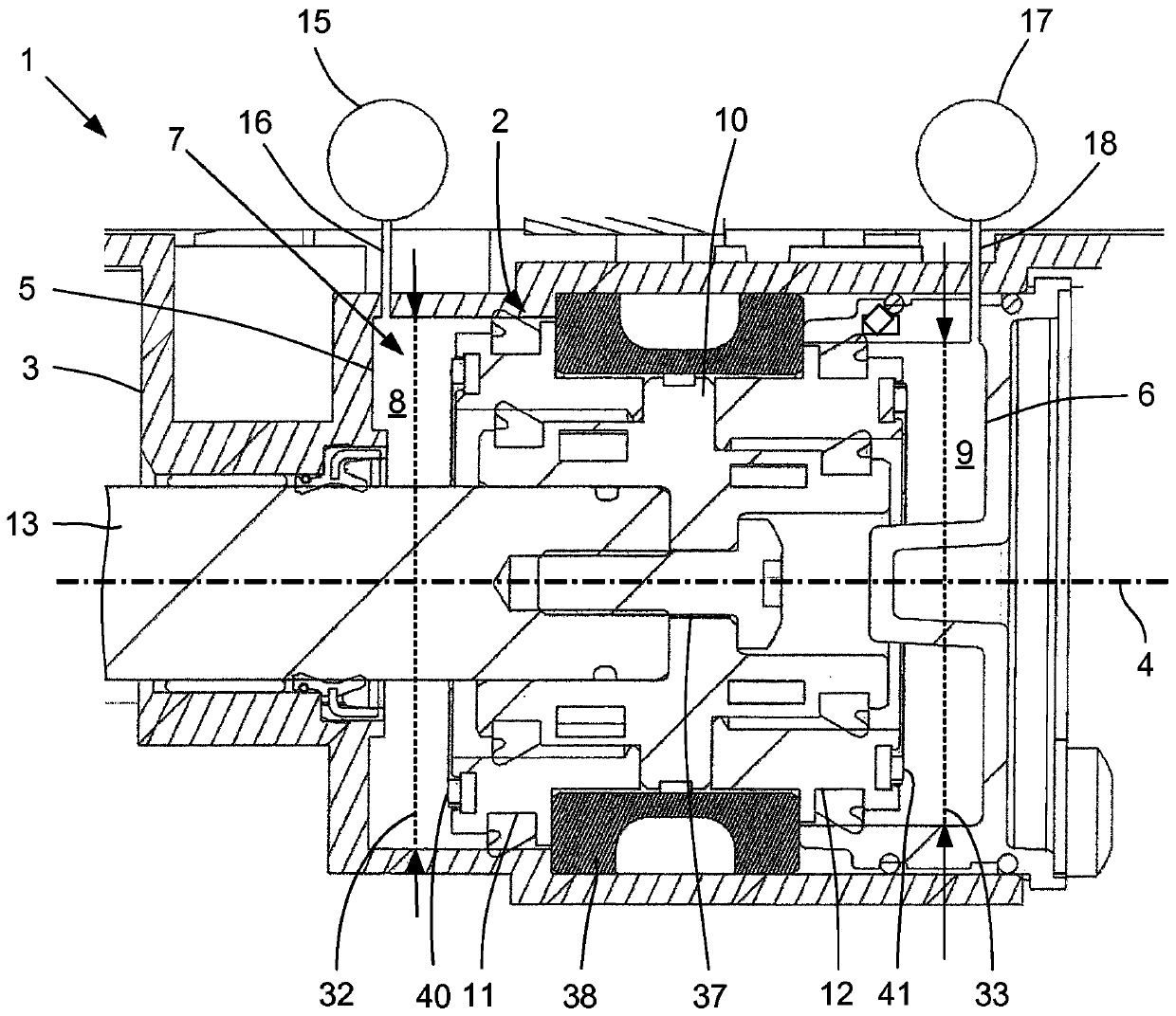
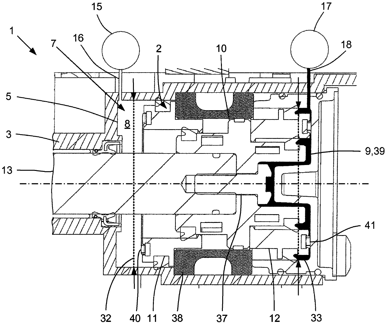
[0051] automatic transmission figure 1 with figure 2 The actuator 1 shown has a piston unit 2 in the form of a shifting piston, which is slidably arranged coaxially with the longitudinal axis 4 in a cylinder housing 3 in the form of a shifting cylinder. The piston unit 2 moves between the first end stop surface 5 and the second end stop surface 6 in the piston chamber 7 of the cylinder housing 3, wherein the piston unit 2 divides the piston chamber 7 into two compressible Air pressure chambers 8 , 9 are sealed relative to each other. The piston unit 2 comprises a main piston 10 and two auxiliary pistons 11 , 12 . Fastened to the main piston 10 is a piston rod 13 , which is mounted slidingly in the cylinder housing 3 and is guided along the longitudinal axis 4 . The connection between the main piston 10 and the piston rod 13 is realized, for example, as a second screw connection 37 .

[0052] The piston rod 13 engages or is operativel...


PUM


Abstract

The invention relates to an actuator (1) for an automated or automatic transmission, having a cylinder housing (3), a piston unit (2), and a piston rod (13). The piston unit (2) is coupled to the piston rod (13) and is arranged in the cylinder housing (3) in a movable manner along an axial longitudinal axis (4). The piston unit (2) separates two pressure chambers (8, 9), which have a variable volume, in the cylinder housing (3), said pressure chambers being used to supply the piston unit (2) with compressed air on both sides. The two pressure chambers (8, 9) are connected to a valve unit (14),by means of which the application of pressure or the ventilation of each of the two pressure chambers (8, 9) can be switched, and an end stop damping device for damping at least one end stop of the piston unit (2) is arranged in the actuator (1). In order to improve the end stop damping device, a pneumatically and mechanically operating damping stage is provided.

Description

technical field [0001] The invention relates to an automatic transmission or an actuator for an automatic transmission having a cylinder housing, a piston unit and a piston rod, wherein the piston unit is coupled to the piston rod and is arranged in the cylinder housing in a manner capable of moving along an axial longitudinal axis , wherein the piston unit separates two variable pressure chambers in the cylinder housing from each other with regard to their volume, by means of which two pressure chambers the piston unit can be charged with compressed air on both sides, wherein the two pressure chambers are connected to the valve unit connection, by means of a valve unit the pressure loading or venting of each of the two pressure chambers can be switched, wherein the end stop damping device for damping at least one end stop of the piston unit is arranged at inside the actuator. The invention also relates to a method of controlling such an actuator. Background technique [0...

Claims


Application Information

Patent Timeline
Patent Type & Authority Applications(China)
IPC IPC(8): F15B15/22F15B11/12F15B11/048F16H63/06
CPCF15B11/048F15B11/123F15B15/226F15B15/228F16H63/065F16H61/30F16J1/005
Inventor 罗曼·普蒂莫·格拉赫丹尼斯·赖曼
Owner ZF CV SYST EURO BV
Why Eureka
Try Eureka