Supercharge Your Innovation With Domain-Expert AI Agents!

Laser marking machine and positioning marking method

A laser marking machine and laser marking technology, applied in laser welding equipment, welding equipment, metal processing and other directions, can solve the problems of low recognition degree of CCD camera, completely coaxial camera center, and unsatisfactory marking effect, etc. It is easy to analyze the reasons and improve the positioning accuracy.

Inactive Publication Date: 2019-11-19
深圳市聚鑫极光科技有限公司 +1
View PDF5 Cites 15 Cited by
  • Summary
  • Abstract
  • Description
  • Claims
  • Application Information

AI Technical Summary

Problems solved by technology

[0002] In the prior art, the marking machine using CCD camera laser positioning, because the galvanometer and the field mirror cannot be completely coaxial with the center of the camera during tooling, the marking effect is not ideal; the lighting is not uniform and the position of the light source is not designed Reasonability will also lead to low recognition of CCD cameras; the three-axis movement components of existing laser marking machines are generally designed as one, and motion interference will occur between different coordinate axes during relative movement, and the simultaneous movement of three axes increases the marking efficiency. Mechanical deviation of machine marking

Method used


Image

  • Laser marking machine and positioning marking method
  • Laser marking machine and positioning marking method

Examples


Embodiment 1

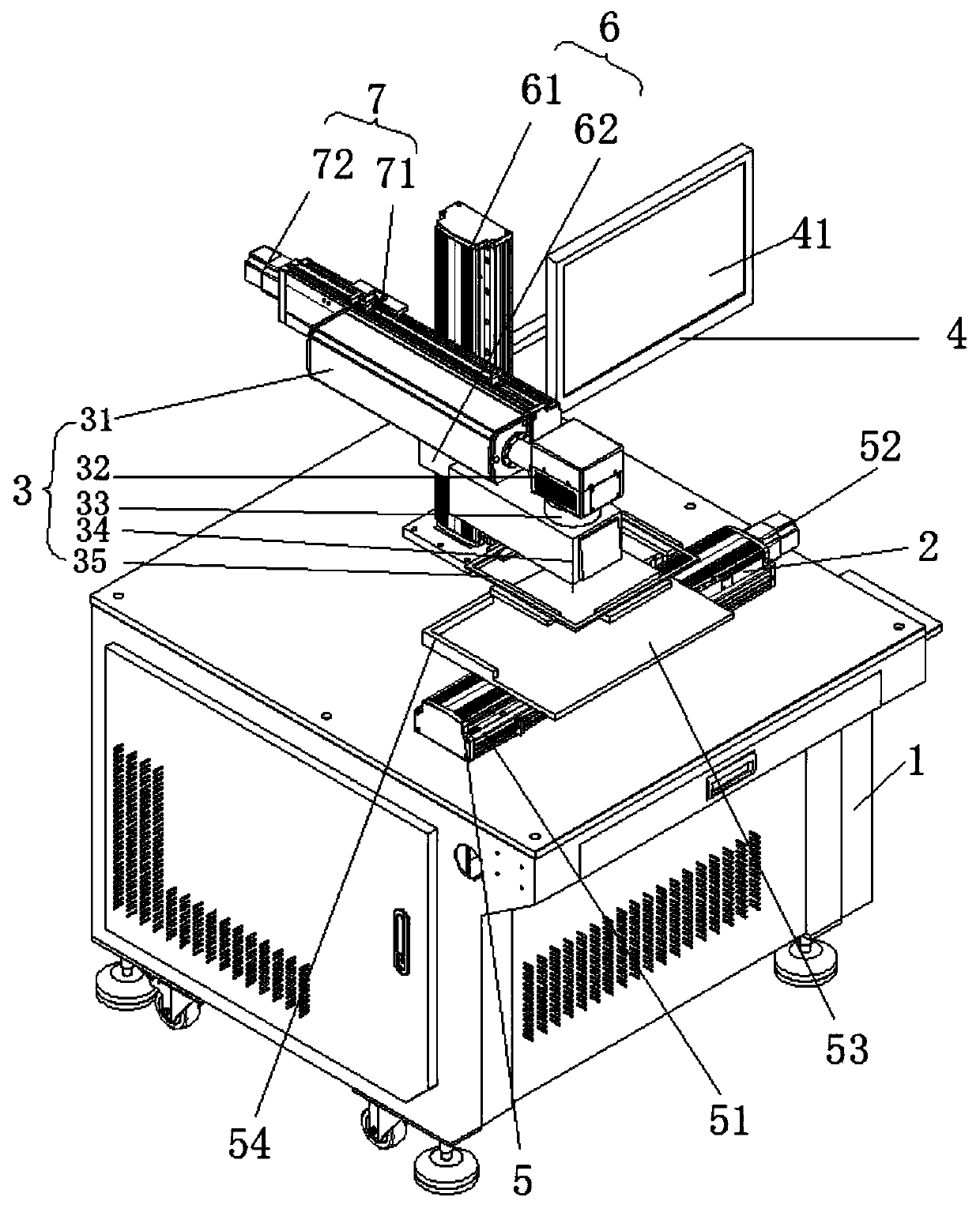
[0034] Such as figure 1 The shown laser marking machine includes a main frame 1, a three-axis motion assembly 2 arranged on the main frame 1, a laser marking assembly 3 fixed on the three-axis motion assembly 2, and a control assembly 4; The moving assembly 2 includes a first transmission assembly 5 arranged on the main frame 1, a lifting assembly 6 located on one side of the first transmission assembly 5, and a second transmission assembly 7 movably installed on the lifting assembly 6; the first transmission assembly 5 It is mainly used for the workpiece disk 53 to move in the left and right directions of the host computer 1 (in this embodiment, the X axis in the coordinate axis), and the second transmission assembly 7 is mainly used to control the movement of the laser marking assembly 3 in the front and rear directions of the host computer 1 ( In this embodiment, it is the Y axis in the coordinate axis); the lifting assembly 6 is mainly used to control the movement of the s...

Embodiment 2

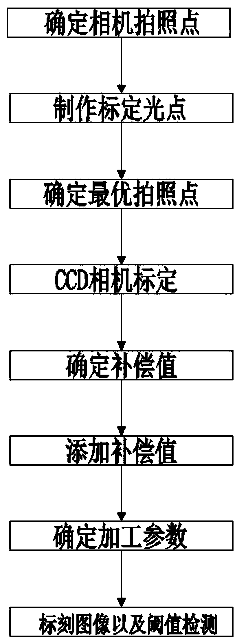
[0046] Such as figure 2 A laser positioning marking method shown includes the following steps:

[0047] Step 1: Determine the photographing point of the camera; turn on the square light source 35, place a blank marking paper on the workpiece tray 53 and align it with the two sides of the right-angle positioning block 54, control the first transmission assembly 5, and move the marking paper to the CCD camera Open the lower end of the industrial computer, open the camera lens, and observe the picture returned by the CCD camera on the touch screen. By adjusting the lifting assembly 6, the field of view of the CCD camera is the same as the size of the marking paper, and on the touch screen 41 Record the height coordinates of the current camera;

[0048] Step 2: Make calibration light spots; turn on the laser generator, and uniformly laser mark 16 groups of light spots on the marking paper by controlling the first transmission component and the second transmission component; the ...


PUM

PropertyMeasurementUnit
widthaaaaaaaaaa

Abstract

The invention discloses a laser marking machine and a positioning marking method. The laser marking machine comprises a main machine table, a three-axis motion assembly, a laser marking assembly and acontrol assembly, wherein the three-axis motion assembly is arranged on the main machine table; and the laser marking assembly is fixed on the three-axis motion assembly. The laser positioning marking method comprises the steps of determining a camera shooting point, making a calibrating light point, determining an optimal shooting point, performing CCD camera calibration, determining a compensation value, adding the compensation value, determining a processing parameter and performing threshold value detection on a marked image. A first transmission assembly and a second transmission assembly adopt split design and are arranged in different areas of the main machine table respectively, so mechanical deviation caused by interference generated during simultaneous motion is avoided; by themethod of adding the compensation value, the positioning precision of the CCD camera is improved; and NG and OK are judged through threshold value detection and pixel value matching value, and the images of unqualified products are transmitted into an industrial personal computer to archive, so that technical personnel can analyze the reason conveniently when a problem occurs in marking.

Description

technical field [0001] The invention relates to the field of automatic laser marking, in particular to a laser marking machine and a positioning marking method. Background technique [0002] In the prior art, the marking machine using CCD camera laser positioning, because the galvanometer and the field mirror cannot be completely coaxial with the center of the camera during tooling, the marking effect is not ideal; the lighting is not uniform and the position of the light source is not designed Reasonability will also lead to low recognition of CCD cameras; the three-axis movement components of existing laser marking machines are generally designed as one, and motion interference will occur between different coordinate axes during relative movement, and the simultaneous movement of three axes increases the marking efficiency. Mechanical deviation of machine marking. Contents of the invention [0003] The present invention aims at solving one of the above-mentioned technic...

Claims


Application Information

Patent Timeline
Patent Type & Authority Applications(China)
IPC IPC(8): B23K26/362B23K26/03B23K26/042B23K26/08B23K26/70
CPCB23K26/032B23K26/042B23K26/0884B23K26/362B23K26/702B23K2101/007
Inventor 符宏军
Owner 深圳市聚鑫极光科技有限公司
Features
  • R&D
  • Intellectual Property
  • Life Sciences
  • Materials
  • Tech Scout
  • Unparalleled Data Quality
  • Higher Quality Content
  • 60% Fewer Hallucinations
Learn More