Flat pushing and conveying mechanism of pipe fitting

A technology of pipe fittings and driving mechanism, applied in conveyors, conveyor objects, transportation and packaging, etc., can solve the problems of smooth and uniform feeding of difficult pipe fittings, falling of difficult pipe fittings one by one, and low feeding efficiency of pipe fittings, etc., to improve the degree of automation , Reasonable effect of structural design

Inactive Publication Date: 2019-11-19
章凌霞
View PDF4 Cites 15 Cited by
  • Summary
  • Abstract
  • Description
  • Claims
  • Application Information

AI Technical Summary

Problems solved by technology

During the production and processing of pipe fittings, it is necessary to sequentially load the pipe fittings that have been processed in the previous process to enable the processing of the subsequent process. After the existing pipe fittings have been processed in the previous process, in order to continue to process the pipe Production and processing, the existing method is to manually feed the pipe fittings one by one, the labor intensity of the workers is high, and the feeding efficiency of the pipe fittings is low, making it difficult to meet the needs of large-scale pipe fitting production and processing. It is difficult for the feeding mechanism to realize the continuous, stable and uniform feeding of the pipe fittings one by one during the feeding process of the pipe fittings. The pipe fittings are stacked together vertically, making it difficult to drop the pipe fittings one by one, and it is difficult for the existing pipe fitting feeding drive mechanism to efficiently and accurately drive the support for pushing the pipe fittings to perform intermittent and smooth translational movements in the horizontal direction, making it difficult to ensure that the pipe fittings move along the horizontal direction. The direction of feeding is intermittently pushed in sequence, which affects the efficiency and quality of normal processing of pipe fittings, and cannot meet the needs of processing and use.

Method used


Image

  • Flat pushing and conveying mechanism of pipe fitting
  • Flat pushing and conveying mechanism of pipe fitting
  • Flat pushing and conveying mechanism of pipe fitting

Examples


Embodiment Construction

[0017] In order to further describe the present invention, a specific implementation of a pipe translational delivery mechanism will be further described below in conjunction with the accompanying drawings. The following examples are explanations of the present invention and the present invention is not limited to the following examples.

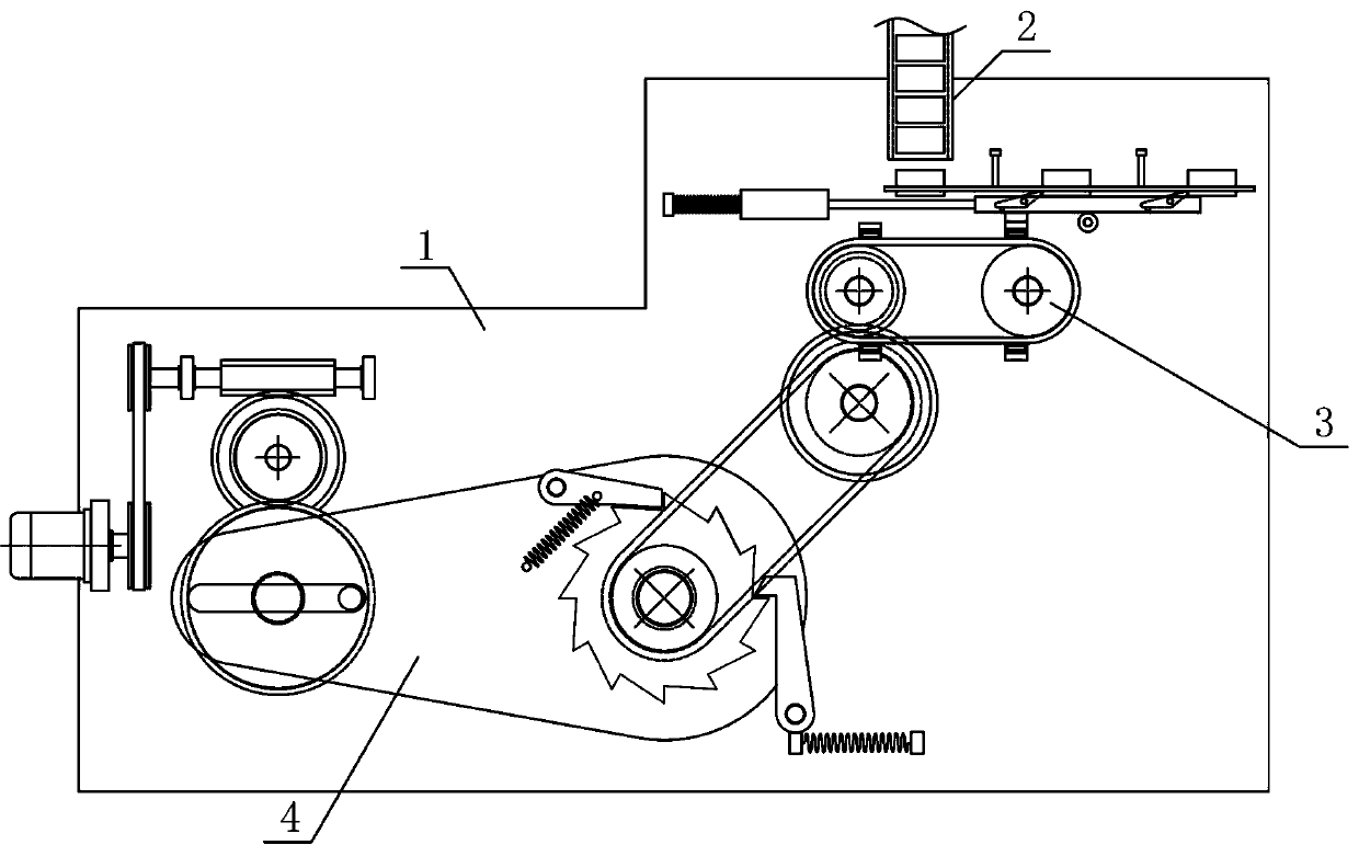
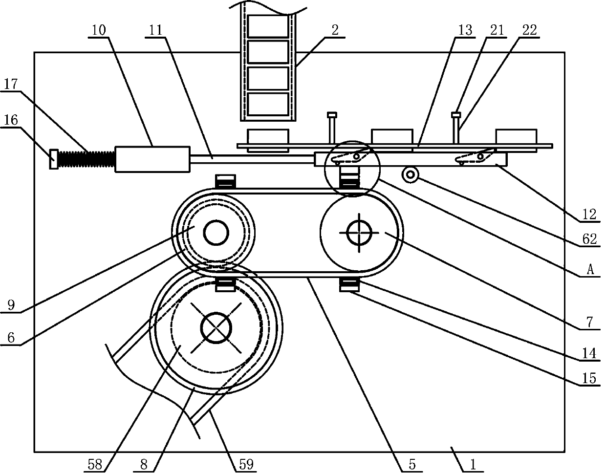
[0018] Such as figure 1 As shown, a pipe fitting translation delivery mechanism of the present invention includes a pipe transfer bracket 1, a pipe drop mechanism 2, a pipe push mechanism 3 and a drive mechanism 4. The tube transfer support 1 vertically fixedly arranged on the side above the tube pushing mechanism 3, and the driving mechanism 4 is horizontally arranged on the tube transfer support 1 on the side below the tube pushing mechanism 3, such as figure 2 As shown, the push tube mechanism 3 of the present invention includes a push tube belt 5, a push tube main runner 6, a push tube auxiliary runner 7, a push tube gear 8, a transmiss...


PUM


Abstract

The invention discloses a flat pushing and conveying mechanism of a pipe fitting, and belongs to the field of workpiece conveying and processing machinery and equipment. A driving mechanism of the flat pushing and conveying mechanism is horizontally arranged on the side, below a pipe pushing mechanism, of a pipe moving support, a plurality of armature sleeves are fixedly arranged on the outer sideof a pipe pushing belt, translation armatures are arranged on the outer sides of the armature sleeves, a pipe pushing support is fixedly arranged at the position, along the end of the pipe pushing belt, of a translation guide rod, the pipe pushing support is provided with a plurality of pipe pushing rotating plates in the horizontal direction, adsorption electromagnets matched with the translation armatures are fixedly arranged on one side below the pipe pushing support, a guide pipe feed pipe is fixedly arranged on the pipe moving support on the supper side of the end part of an guide pipe bearing rod, the middle part of one side of a reciprocating pendulum plate is vertically and rotatably connected with a transfer rotating shaft, and a transfer ratchet wheel is fixedly and coaxially arranged on the transfer rotating shaft on the outer side of the reciprocating pendulum plate. According to the flat pushing and conveying mechanism of the pipe fitting, the structure design is reasonable, the pipe fitting can be smoothly and accurately pushed and loaded in sequence and intermittently in the horizontal direction, the automation degree of the pipe fitting transfer is improved, and the needs of processing and use are met.

Description

technical field [0001] The invention belongs to the field of workpiece conveying and processing machinery, and in particular relates to a pipe fitting translational conveying mechanism, which is mainly applied to the continuous conveying and processing of pipe fittings. Background technique [0002] Pipe fittings refer to workpieces with a cylindrical structure. There are many types of pipe fittings. Different pipe fittings use different materials. The quality of the material directly determines the quality of the pipe fittings. Pipe fittings are necessary materials for construction engineering and mechanical equipment. A general term for components that play the roles of connection, control, direction change, flow diversion, sealing, support, etc. Steel pipe fittings are the most important type of pipe fittings. Steel pipe fittings are pressure-bearing pipe fittings. According to different processing techniques, steel pipe fittings can be divided into: butt welding pipe fit...

Claims


Application Information

Patent Timeline
Patent Type & Authority Applications(China)
IPC IPC(8): B65G17/12B65G47/84
CPCB65G17/12B65G47/844B65G2201/0276
Inventor 章凌霞
Owner 章凌霞
Why Eureka
Try Eureka