Garbage treating furnace capable of improving controllability of technological parameters

A technology of waste treatment and process parameters, applied in gasification process, coke oven, petroleum industry, etc., can solve the problems of land occupation, flue gas purification treatment and discharge burden, threat of groundwater resources, etc., achieve continuous feeding and improve treatment efficiency effect

Pending Publication Date: 2019-11-19
四川火尔赤清洁能源有限公司
View PDF0 Cites 0 Cited by
  • Summary
  • Abstract
  • Description
  • Claims
  • Application Information

AI Technical Summary

Problems solved by technology

Solid waste landfill treatment of domestic waste not only occupies land, but also poses a great threat to groundwater resources; although waste incineration can achieve certain energy conversion and reduce the space requirements for post-processing, when incinerating ...

Method used


Image

  • Garbage treating furnace capable of improving controllability of technological parameters

Examples


Embodiment 1

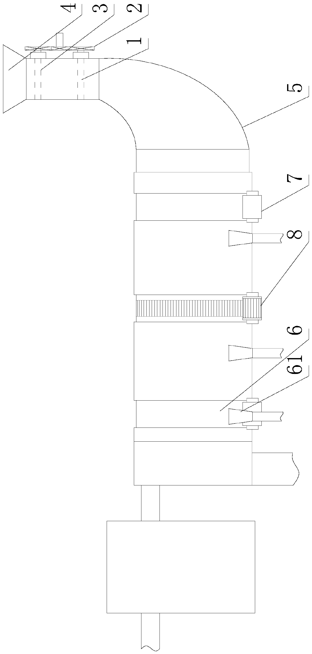
[0039] Such as figure 1 As shown, a garbage treatment furnace that can improve the controllability of process parameters is a pyrolysis furnace or a gasification furnace, and the treatment furnace includes a furnace body 6 for heating garbage, and the furnace body 6 It is in the shape of a cylinder with openings at both ends, and the opening at one end is used as the material feeding end, and the opening at the other end is used as the material discharging end;

[0040] The furnace body 6 is also provided with a material transfer mechanism, and the material transfer mechanism is used to realize the transfer of materials in the furnace body 6: from the feed end to the discharge end;

[0041] It also includes a heating assembly 61 for heating the furnace body 6. There are at least three groups of the heating assembly 61, the furnace body part at the feed end, the furnace body part at the discharge end, the furnace body part at the feed end and the discharge end. The furnace bod...

Embodiment 2

[0046] The present embodiment is further limited on the basis of embodiment 1, as figure 1 As shown, as a specific implementation of the material transfer mechanism, it is set as follows: the material transfer mechanism is a plurality of deflectors installed on the inner wall of the furnace body 6, and the deflectors are rotated by the furnace body 6 to push the material from the The feed end is transferred to the discharge end. With this solution, the furnace body 6 is used to drive the deflector to rotate. During the rotation of the deflector, a plurality of deflectors work together, and the deflectors cooperate to provide a thrust towards the discharge end of the material to realize the transmission. With this scheme, the deflector is a push plate welded on the inner wall of the furnace body 6 to achieve the corresponding purpose. This type of material transfer mechanism does not require additional power parts and transmission parts, so it not only has a simple structure an...

Embodiment 3

[0050] The present embodiment is further limited on the basis of embodiment 1, as figure 1 As shown, the feed end of the furnace body 6 is also connected with a feed pipe 5, and the furnace body 6 can rotate around its own axis independently of the feed pipe 5;

[0051] A first valve plate 1 and a second valve plate 3 are installed on the feed pipe 5, and both the first valve plate 1 and the second valve plate 3 are used to control the conduction state of the feed pipe 5;

[0052] In the extending direction of the feed pipe 5, the first valve plate 1 and the second valve plate 3 are installed in different positions;

[0053] It also includes a linkage device 2, which is used to link the first valve plate 1 and the second valve plate 3, so that during the movement of the first valve plate 1 and the second valve plate 3, either one is in the cut-off position. During the state of feeding pipe 5, the other is in the state of conducting feeding pipe 5. In this solution, it is set...


PUM


Abstract

The invention discloses a garbage treating furnace capable of improving controllability of technological parameters. The garbage treating furnace is a pyrolysis furnace or gasification furnace. The treating furnace includes a furnace body for heating garbage; the furnace body has two ends which are both of a cylindrical shape with an opening, wherein the opening in one end is used as a material feeding end and the opening in the other end is used as a material discharging end. The treating furnace also includes heating assemblies used for heating the furnace body, wherein the number of the heating assemblies is at least three, and a furnace body part at the material feeding end, a furnace body part at the material discharging end and a furnace body part located between the furnace body part at the material feeding end and the furnace body part at the material discharging end are heated by the different heating assemblies respectively. According to the structural design of the garbage treating furnace, through sectional heating, the temperature environment of garbage in all sections of the furnace body can be conveniently controlled, and the purpose of improving the controllabilityof technological parameters is achieved.

Description

technical field [0001] The invention relates to the technical field of energy-saving and environment-friendly equipment, in particular to a garbage treatment furnace capable of improving the controllability of process parameters. Background technique [0002] With the rapid development of my country's social economy, the acceleration of urbanization and the rapid improvement of people's living standards, the garbage and waste generated in the process of urban production and life have also increased rapidly, and the situation of domestic garbage occupying land and polluting the environment has become more and more obvious. The massive increase of domestic garbage makes it more and more difficult to dispose of garbage, and the resulting environmental pollution and other issues have gradually aroused widespread concern from all walks of life. [0003] In the process of traditional waste disposal, waste with no reuse value is generally selected for landfill or incineration. Soli...

Claims


Application Information

Patent Timeline
IPC IPC(8): C10B53/00C10J3/00
CPCC10B53/00C10J3/00C10J2300/0946
Inventor 彭罡彭琪
Owner 四川火尔赤清洁能源有限公司
Why Eureka
Try Eureka