
A ship energy-saving power generation equipment

An energy-saving power generation and equipment technology, applied in wind power generation, mechanical equipment, energy storage, etc., can solve problems such as uncontrollable, insufficient power generation, transmission wear, etc., achieve stable and efficient operation, improve practical life, and improve operating efficiency.

Active Publication Date: 2020-12-29
BINZHOU POLYTECHNIC
View PDF1 Cites 0 Cited by
  • Summary
  • Abstract
  • Description
  • Claims
  • Application Information

AI Technical Summary

Problems solved by technology

However, the energy-saving power generation device proposed in this patent only combines wind power and water power to form a power generation device. It cannot control the rotation direction and wind speed of the inner rotor and outer rotor respectively driven by wind power and water power. When the wind power and water power rotate in the same direction, it is not enough to generate electricity. The speed of rotation cannot be controlled, and multi-gear afterburner transmission is used, which causes transmission wear and tear. It is impossible to realize remote monitoring of the power generation device, and it is impossible to warn the failure of the power generation device in advance, which brings safety hazards to ship navigation.

Method used


Image

  • A ship energy-saving power generation equipment
  • A ship energy-saving power generation equipment
  • A ship energy-saving power generation equipment

Examples


Embodiment Construction

[0020] The technical solutions in the embodiments of the present invention will be described clearly and completely in further detail below in conjunction with the accompanying drawings in the embodiments of the present invention. Based on the embodiments of the present invention, all other embodiments obtained by persons of ordinary skill in the art without making creative efforts belong to the protection scope of the present invention.

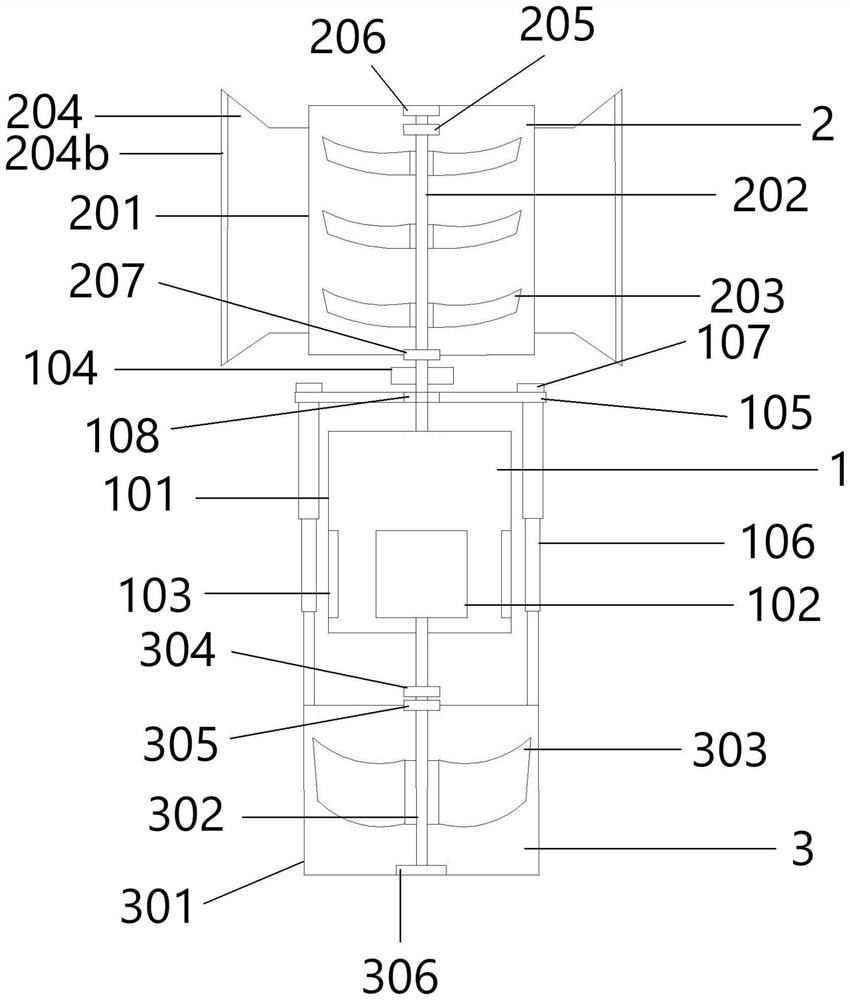
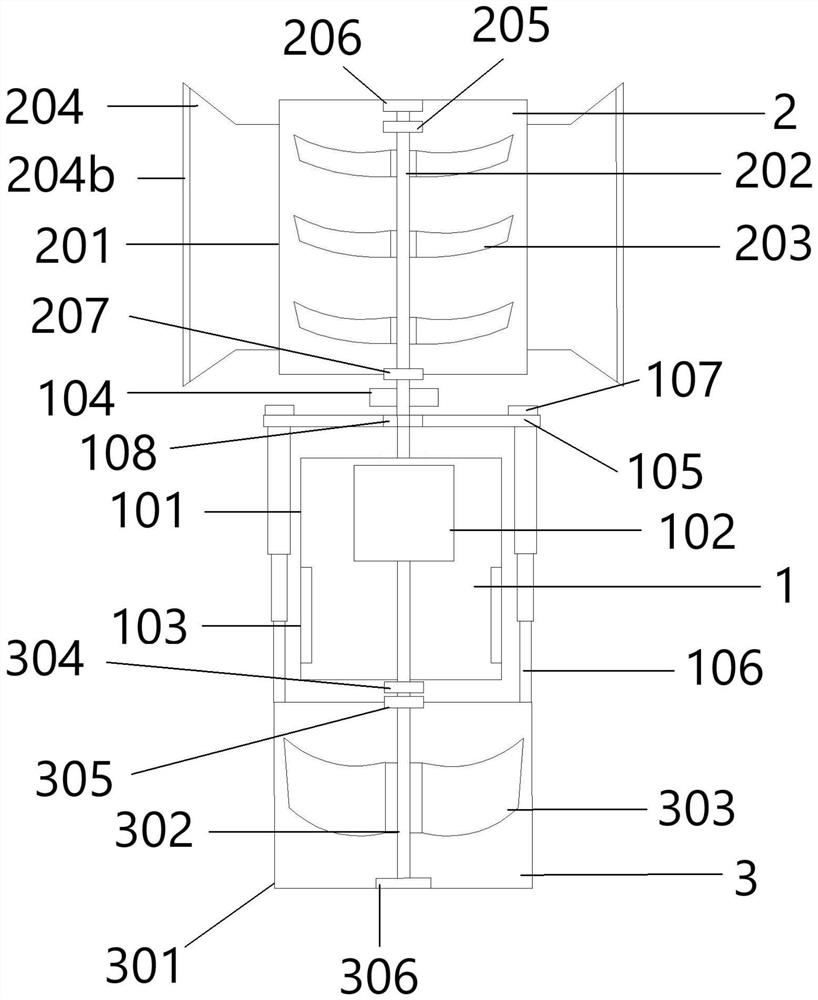
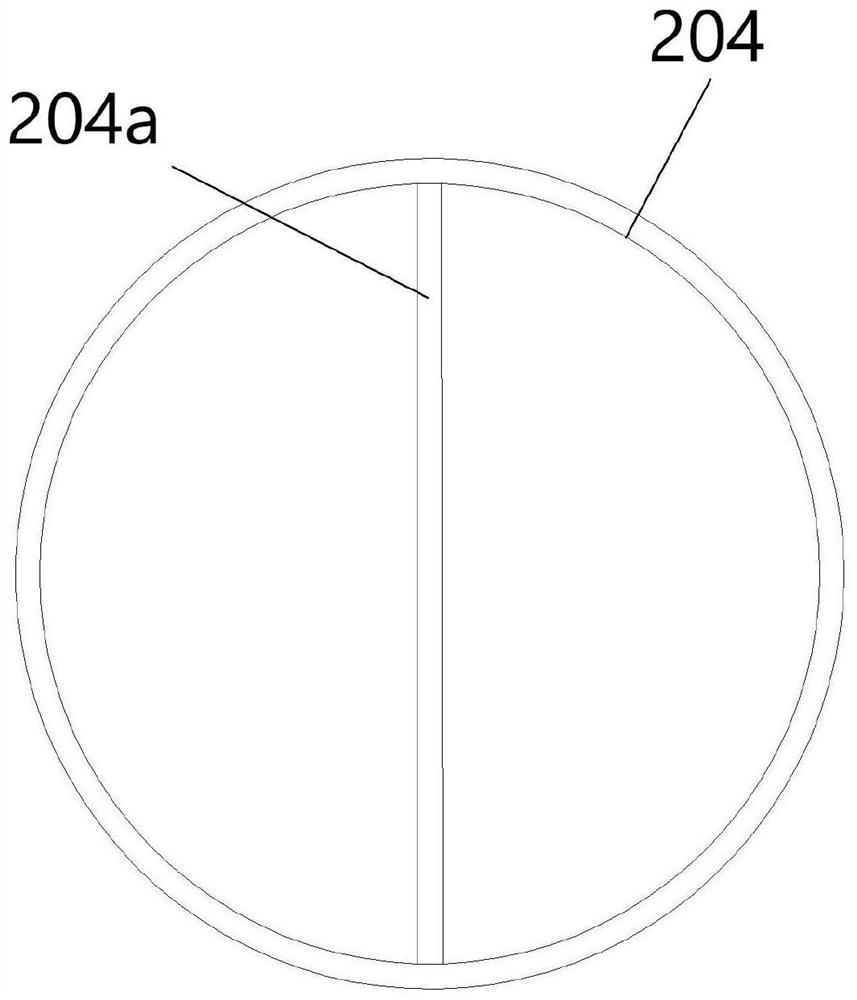
[0021] Such as Figure 1-4 As shown, a ship energy-saving power generation equipment includes a power generation unit 1, a wind power unit 2 located above the power generation unit 1, and a hydraulic unit 3 located below the power generation unit 1. The power generation unit 1 includes an outer rotor 101, an inner rotor 102 and a slip ring 104, the upper part of the outer rotor 101 is connected to the wind power transmission shaft 202 of the wind power unit 2, the wind power transmission shaft 202 is connected to the bellows 201 through the ...


PUM


Abstract

The invention proposes a ship energy-saving power generation equipment, which includes a power generation unit, a wind power unit located above the power generation unit, and a water power unit located below the power generation unit. The power generation unit includes an outer rotor, an inner rotor and a collector ring, and the upper part of the outer rotor is connected to the wind power unit. The wind power transmission shaft is connected to the bellows through the first wind power fixed bearing and the second wind power fixed bearing. The wind power transmission shaft is equipped with evenly distributed wind blades, and the upper part of the wind power transmission shaft is also equipped with a monitoring device for the direction of rotation and speed of the wind power transmission shaft. The wind speed sensor, the outer side of the bellows is provided with a plurality of air inlets and outlets for wind in and out, the air collectors are provided with a rotating shaft to control the rotation of the windshield, and the rotating shaft is connected to the control motor; the rotating shaft and the windshield designed in the present invention realize the wind direction and wind power transmission The speed control avoids the problem of the outer rotor and the inner rotor rotating in the same direction, making the equipment more stable and efficient; the designed expander controls the inner rotor to move up and down in the outer rotor and enables the water tank to enter the water and leave the water surface.

Description

technical field [0001] The invention relates to the technical field of energy-saving power generation, in particular to ship energy-saving power generation equipment. Background technique [0002] With the rapid development of the shipbuilding industry, there are more and more large ships, and the tonnage and displacement of ships are getting larger and larger. However, most of the ships now use fuel oil as power, which will cause fuel oil, which takes a long time to form, to consume more and more energy. The bigger it is, and the fuel will produce a lot of exhaust gas after the fuel provides power and work, polluting the air and water environment. Long-distance voyages need to carry a large amount of reserve fuel, causing power loss for the ship, or going to the seaport to refuel is a waste of time and efficiency. [0003] Some ships now use electricity or nuclear energy as power. Electricity is a way to transform to clean energy. There are many ways to generate electricity...

Claims


Application Information

Patent Timeline
Patent Type & Authority Patents(China)
IPC IPC(8): F03D9/11F03D9/32F03D17/00F03D80/00F03D9/00F03B13/00F03B11/00F03B3/00F03B15/00
CPCF03B3/00F03B11/00F03B11/008F03B13/00F03B15/00F03B15/005F03D9/008F03D9/11F03D9/32F03D17/00F03D80/00Y02E10/20Y02E10/72Y02E10/728Y02E70/30
Inventor 陆宝成翟伟赵志强赵贤东王锐刘明明
Owner BINZHOU POLYTECHNIC
Learn More