

Oil circulation device and method of a pressure changing device
A technology for changing devices and circulation devices, which is applied in the directions of transmission parts, engine lubrication, gear lubrication/cooling, etc. It can solve the problems of large space occupation, independent oil supply structure, complexity, etc., and achieve simplified oil supply methods and reduced costs , The effect of simplifying the process
- Summary
- Abstract
- Description
- Claims
- Application Information
AI Technical Summary
Problems solved by technology
Method used
Image

Examples
Embodiment 1
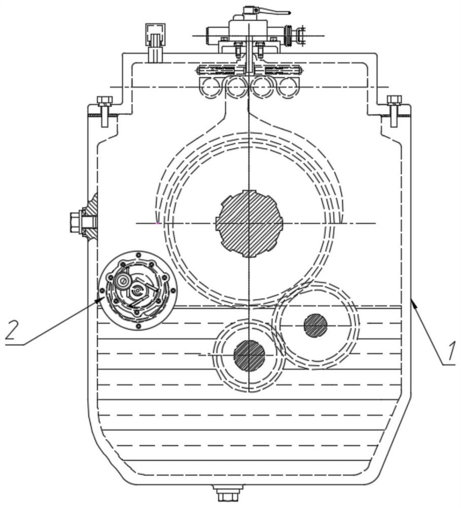
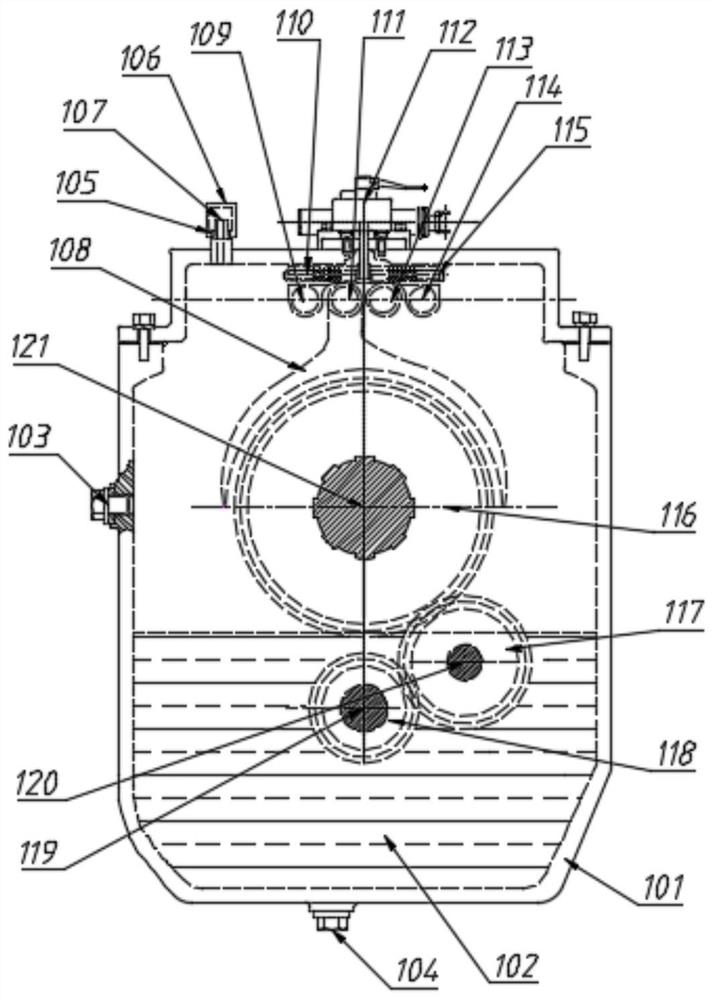
[0060] Such as Figure 2-7 As shown, an oil circulation device of a pressure changing device includes an oil supply device and a pressure changing device 2; the oil supply device is a gearbox 1; the gearbox 1 includes a housing 101, and the pressure changing device 2 It is fixedly installed in the casing 101 of the gearbox 1 .
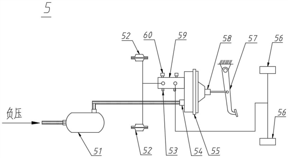
[0061] The pressure changing device 2 includes a flange 201, a pump body 202, a negative pressure air inlet 203 and a gas pipe joint 204;
[0062] The flange 201 is arranged on the front end of the pump body 202; the pump body 202 contains a vacuum chamber 205; the negative pressure inlet 203 is arranged on the flange 201, and is connected with the vacuum chamber 205 communicates; the air pipe joint 204 is fixedly installed on the negative pressure air inlet 203; the air pipe joint 204 is connected with the vacuum booster servo braking system circuit to provide negative pressure for the vacuum booster.
[0063] The gearbox 1 is provided with an oil p...
Embodiment 2
[0077] Such as Figure 10-12 As shown, the structural principle of this embodiment is similar to that of Embodiment 1, and the difference with Embodiment 1 is:
[0078] 1) The pressure changing device 2 is fixedly installed outside the casing 101 of the gearbox 1;
[0079] 2) Cancel the pressure changing device mounting plate 206;
[0080] 3) The pressure changing device 2 is added: a pressure changing device housing 2031 , a front support base 2032 and a rear support base 2033 .
[0081] The pressure changing device casing 2031 covers the outside of the pressure changing device 2;
[0082] One side of the front support base 2032 and the rear support base 2033 are fixed on the pressure changing device housing 2031, and the other side is fixed on the housing 101;
[0083] The pressure changing device 2 is fixedly installed outside the casing 101 through the front support base 2032 and the rear support base 2033 .
[0084] Further, the rear support seat 2033 is provided with...
Embodiment 3
[0090] Such as Figure 13-15 As shown, the structural principle of this embodiment is similar to that of Embodiment 2, and the difference with Embodiment 2 is;
[0091] 1) Cancel the oil inlet hole 2034 of the rear support seat;
[0092] 2) The pressure changing device 2 adds a tail support seat 2036, and an oil inlet hole 2037 of the tail support seat is set in the tail support seat 2036 to replace the oil inlet hole 2034 of the rear support seat.
[0093] One end of the oil inlet hole 2037 of the tail support seat communicates with the central hole 2026 of the rotating shaft 2023 , and the other end communicates with the inside of the housing 101 and is below the oil level of the oil pool 102 .
[0094]Due to the effect of vacuum suction, the oil in the gearbox 1 enters the center hole 2026 of the rotating shaft 2023 from the oil inlet hole 2037 of the tail support seat, and the oil in the center hole 2026 is due to negative pressure. Function, through the oil throwing thr...
PUM
 Abstract
Description
Claims
Application Information