Distribution beam loading system for metal truss radome test and installation method

A technology of loading system and distributing beams, which is applied in the field of construction engineering, can solve the problems of complex force transmission, large total load value, large volume, etc., achieve a high degree of standardization, reduce installation difficulty, and avoid personnel safety accidents

Active Publication Date: 2019-11-19
HARBIN TOPFRP COMPOSITE +1
View PDF8 Cites 0 Cited by
  • Summary
  • Abstract
  • Description
  • Claims
  • Application Information

AI Technical Summary

Problems solved by technology

[0003] In order to solve the problem that the metal truss radome test model in the prior art has a large volume, complex force transmission, and a large total load value, which leads to the difficulty and particularity of the design of the test loading system, The distribution beam loading system and installation method for metal truss radome tests are now provided;

Method used


Image

  • Distribution beam loading system for metal truss radome test and installation method
  • Distribution beam loading system for metal truss radome test and installation method
  • Distribution beam loading system for metal truss radome test and installation method

Examples


specific Embodiment approach 1

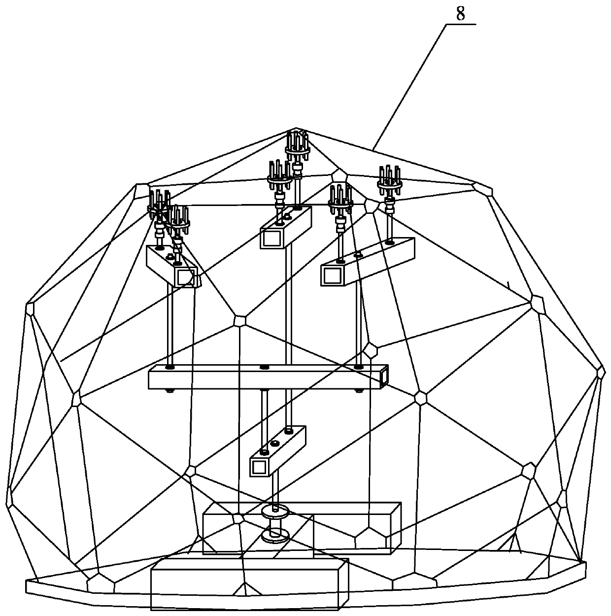
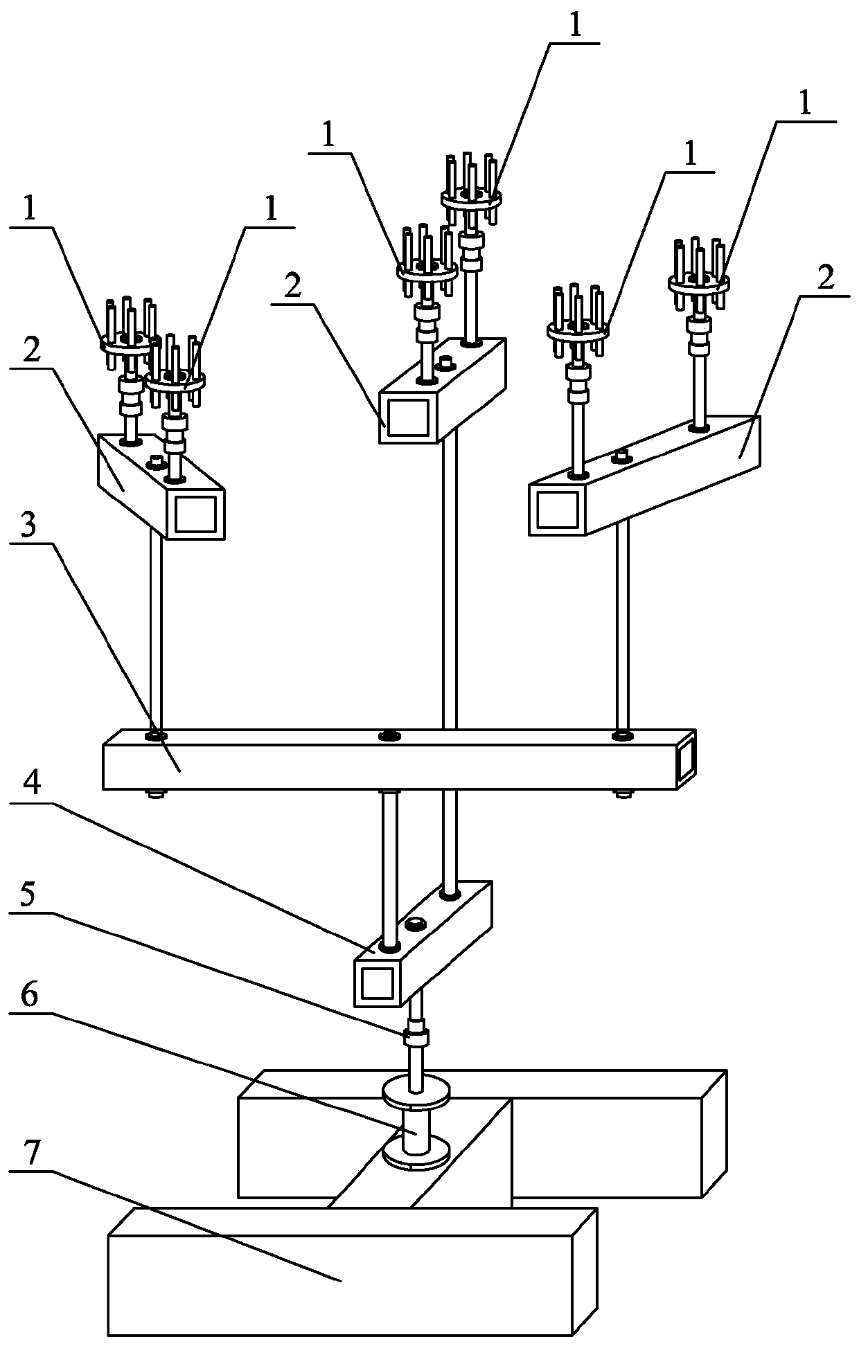
[0024] Specific implementation mode one, combining figure 1 and figure 2 This embodiment is described. In this embodiment, a distribution beam loading system for metal truss radome tests is provided. The loading system includes a middle distribution beam mechanism 3, a lower distribution beam mechanism 4, a total force sensor 5, a jack 6, Force beam 7, three upper distribution beam mechanisms 2 and six node devices 1;

[0025] The reaction beam 7 is arranged on the inside of the radome 8, and the reaction beam 7 is fixed on the bottom plate in the radome 8, and the jack 6 is arranged on the upper surface of the reaction beam 7, and the cylinder body of the jack 6 and the reaction The force beam 7 is fixedly connected, the hydraulic output rod of the jack 6 is detachably connected to the shell of the total force sensor 5, the input end of the total force sensor 5 is detachably connected to the lower distribution beam mechanism 4, and the middle distribution beam mechanism 3 i...

specific Embodiment approach 2

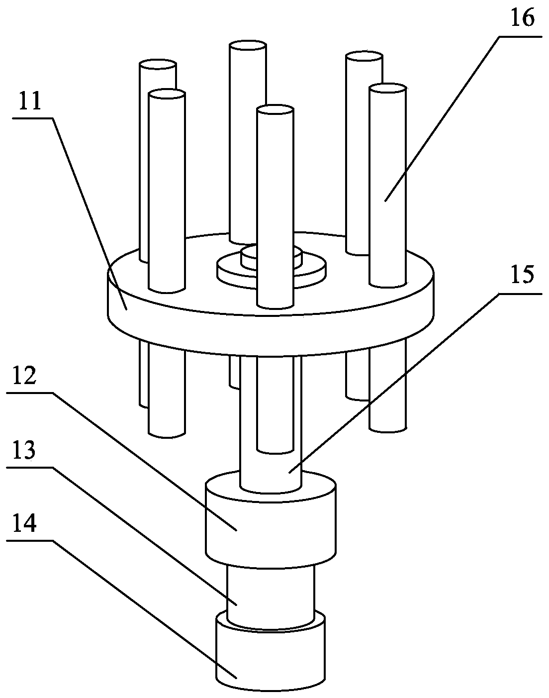
[0027] Specific implementation mode two, combining image 3 This embodiment is described. This embodiment is to further limit the joint device 1 described in the first specific embodiment. The joint device 1 includes a joint plate 11, a universal bearing 12, a variable diameter steel rod 13, a joint force sensor 14, 15 high-strength bolts and M bolts 16, M is a positive integer, the two ends of the variable diameter steel rod 13 are provided with threaded sections, the center of the node plate 11 is provided with a central hole, and the end surface of the node plate 11 is evenly provided with M threads along the circumferential direction Holes A, each threaded hole A is provided with a bolt 16, and each bolt 16 is threaded with a threaded hole A, one end of the high-strength bolt 15 is arranged in the center hole, and the node plate 11 is connected with the One end of the high-strength bolt 15 is fixedly connected, the universal bearing 12 is arranged under the node plate 11, ...

specific Embodiment approach 3

[0029] Specific implementation mode three, combining Figure 4Describe this embodiment, this embodiment is to further limit the upper distribution beam mechanism 2 described in the first specific embodiment, the upper distribution beam mechanism 2 includes the upper distribution beam main body 21, the upper threaded steel bar A22 and the upper layer threaded steel bar B23, The upper distribution beam main body 21 is a box-shaped cross-section beam, and a group of opposite side walls in the upper distribution beam main body 21 are respectively provided with a through hole A, a connecting hole A and a through hole B in sequence along the length direction, and each side The through hole A and the through hole B on the wall are arranged symmetrically along the midline of the long side of the side wall where it is located, the connecting hole A is set on the long side midline of the side wall where it is located, and the axis of the connecting hole A, the axis of the through hole A ...


PUM


Abstract

A distribution beam loading system for metal truss radome test and an installation method belong to the field of building engineering, which are mainly used for solving the problem that a metal trussradome test model in the prior art is large in volume, is complex in transmission force, and is large in total load value that needs to be applied, resulting in design of a test loading system to be more difficult and specific. The system mainly includes a middle-layer distribution beam mechanism, a lower-layer distribution beam mechanism, a total force sensor, a jack, a counterforce beam, three upper-layer distribution beam mechanisms and six node devices, and high-strength bolts pass through node discs of loading nodes and are sequentially and downwardly connected with universal bearings, node force sensors, the upper-layer distribution beam mechanisms, the middle-layer distribution beam mechanism, the lower-layer distribution beam mechanism, the total force sensor, the jack, the counterforce beam and a radome. The system is mainly used for a loading system of the metal truss radome test.

Description

technical field [0001] The invention relates to a distribution beam loading system and an installation method for metal truss radome tests, and belongs to the field of construction engineering. Background technique [0002] It is necessary to carry out overall model tests on unconventional spatial structures: the correct application of various structural analysis techniques is inseparable from the correct modeling of the structure, and the modeling process of a new system, and the correct cognition of structural analysis engineers Related to the empirical basis, the overall model test can guide the structural analysis and modeling and check the calculation results, thus enlightening people to understand the engineering structure more comprehensively. The key to successful model testing is to determine the test loading system and ensure that the applied load reflects the mechanical performance of the space structure as much as possible. Due to the large volume of the metal t...

Claims


Application Information

Patent Timeline
IPC IPC(8): G01M13/00
CPCG01M13/00
Inventor 孙宝华孟松孙东岩王乐武岳
Owner HARBIN TOPFRP COMPOSITE
Why Eureka
Try Eureka