Input and output computer card and control method

A technology of input and output, board card, applied in the direction of program control, computer control, general control system, etc., can solve the problem of unable to realize the self-test of system hardware circuit, unable to realize contactors and relays, etc., to achieve self-test function, simplify The effect of structure and function

Inactive Publication Date: 2019-11-19
XIAN YONGDIAN ELECTRIC
View PDF5 Cites 0 Cited by
  • Summary
  • Abstract
  • Description
  • Claims
  • Application Information

AI Technical Summary

Problems solved by technology

[0004] The purpose of the present invention is to provide an input and output board and control method, which solves the problem that the existing products cannot realize the digital quantity data collection of the traction system with a large number of contactors and relays, and cannot realize the self-test function of the system hardware circuit

Method used


Image

  • Input and output computer card and control method
  • Input and output computer card and control method

Examples


Embodiment Construction

[0031] The present invention is described in further detail below in conjunction with accompanying drawing:

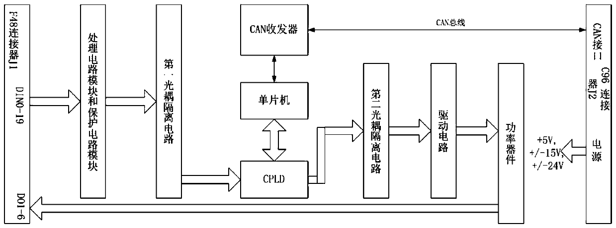
[0032] Such as figure 1 As shown, an input and output board, the size of the input and output board is 100mm×220mm or 100mm×160mm, and the upper surface of the input and output board is installed with J from left to right. 1 Connectors, processing circuit modules, protection circuit modules, optocoupler isolation circuits, CPLDs, microcontrollers, CAN transceivers, optocoupler isolation circuits, drive circuits, power devices, J 2 Connector.

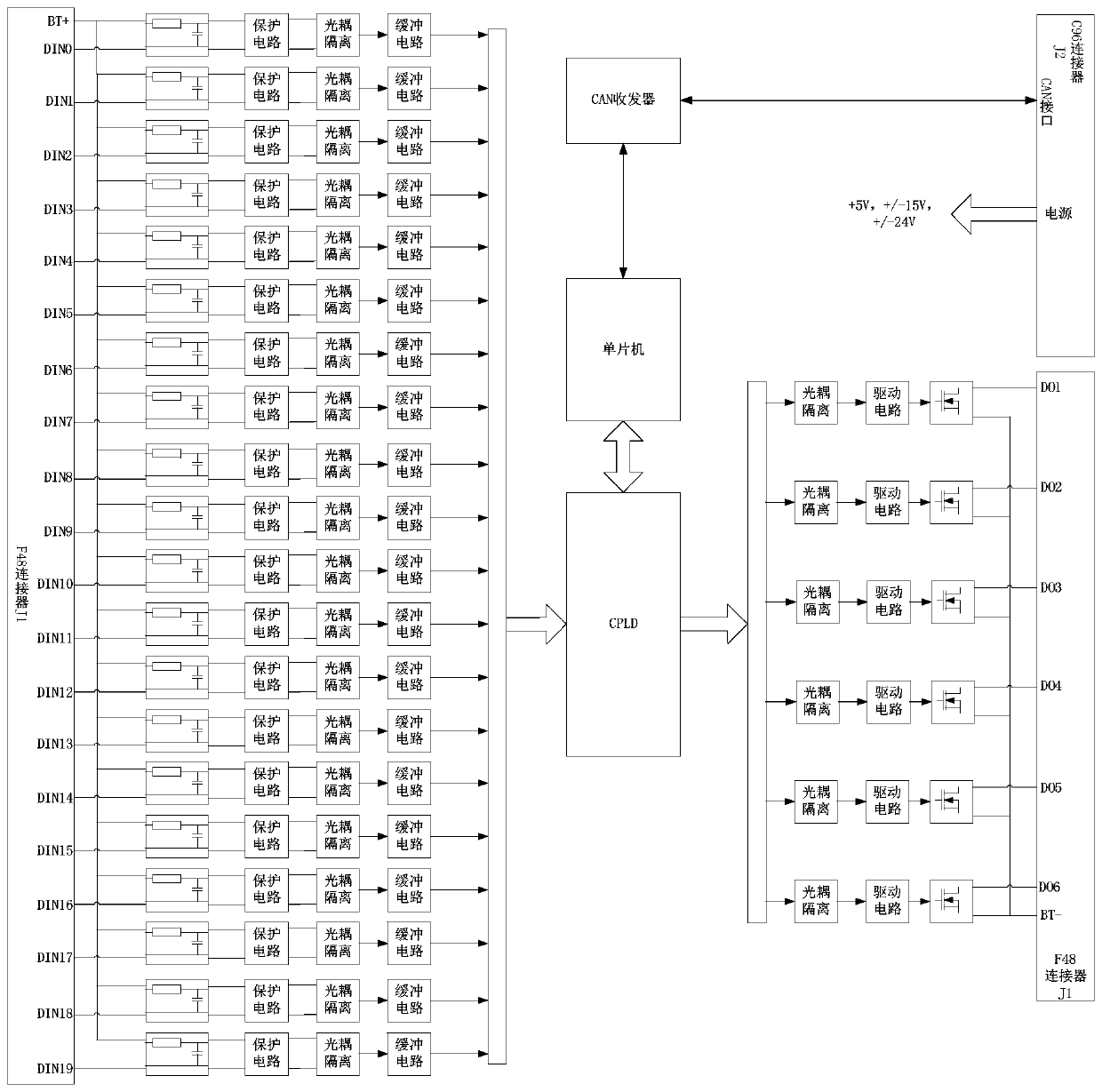
[0033] J 1 Several digital input signal channels and several digital output signal channels are arranged on the connector.

[0034] A number of digital input signal channels are preferably DIN0-DIN19, a total of 20 channels, DIN0-DIN19 channels are electrically connected to the processing circuit module and the protection circuit module, used for digital input signal input, the input level signal passes through the processing ...


PUM


Abstract

The invention provides an input and output computer card. A J1 connector, a processing circuit module, a protecting circuit module, a first optocoupler isolation circuit, a complex programmable logicdevice (CPLD), a single chip, a controller area network (CAN) transceiver, a second optocoupler isolation circuit, a driving circuit, a power device and a J2 connector are installed from the left to the right in turn on an upper surface of the input and output computer card; several digital quantity input signal channels and several digital quantity output signal channels are arranged on the J1 connector, the several digital quantity input signal channels are electrically connected to the processing circuit module and the protecting circuit channel, the processing circuit module and the protecting circuit module are separately connected to the first optocoupler isolation circuit, the first optocoupler isolation circuit is connected to the CPLD, the CPLD is electrically connected to the single chip, the single chip is connected to the CAN transceiver, through a CAN bus, the CAN transceiver is connected to a CAN interface arranged on the J2 connector, the CPLD is electrically connected to the second optocoupler isolation circuit, the second optocoupler isolation circuit is electrically connected to the driving circuit module, and the driving circuit module is electrically connected to the power device.

Description

technical field [0001] The invention belongs to the technical field of rail transit traction control, and in particular relates to an input-output board and a control method. Background technique [0002] In terms of electrical traction control of EMUs or locomotives in the field of rail transit, under normal circumstances, the number of contactors and relays is not too large, and the general-purpose digital input and output acquisition boards can basically meet the digital acquisition requirements; but in some other locomotive traction systems applications Among them, there are a lot of contactors and relays, and it is also required to realize the self-test function of the hardware circuit of the system. In this way, it is difficult for the general digital input and output acquisition board to meet the digital acquisition requirements. [0003] Existing products can realize digital input and output acquisition boards, which can basically meet the requirements of digital acq...

Claims


Application Information

Patent Timeline
Patent Type & Authority Applications(China)
IPC IPC(8): G05B19/042
CPCG05B19/0423G05B2219/25257
Inventor 陈建峰高锦慧尚林岳赵豆左瑜君
Owner XIAN YONGDIAN ELECTRIC
Why Eureka
Try Eureka