Magnetic field sensing device

A magnetic field sensing and magnetic field technology, applied in the field of magnetic field sensing devices, can solve the problems of large volume, large current, cost of transportation and detection time of the detection system, etc.

Active Publication Date: 2020-12-08
ISENTEK INC
View PDF13 Cites 0 Cited by
  • Summary
  • Abstract
  • Description
  • Claims
  • Application Information

AI Technical Summary

Problems solved by technology

However, in order to generate a large-scale detection magnetic field to detect multiple magnetic field devices at one time, the detection system needs a larger volume and requires a larger current.
Moreover, a large amount of time for transportation and testing is also required in the testing process, resulting in an increase in the production cost and production time of the magnetic field sensing device.

Method used


Image

  • Magnetic field sensing device
  • Magnetic field sensing device
  • Magnetic field sensing device

Examples


Embodiment Construction

[0056] Reference will now be made in detail to the exemplary embodiments of the present invention, examples of which are illustrated in the accompanying drawings. Wherever possible, the same reference numbers will be used in the drawings and description to refer to the same or like parts.

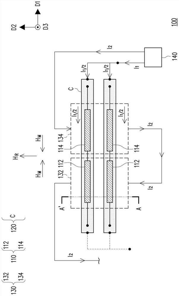
[0057] In order to facilitate the description of the configuration of the magnetic field sensing device in the embodiment of the present invention, the magnetic field sensing device can be regarded as being in a space formed by a direction D1, a direction D2 and a direction D3, wherein the directions D1, D2, and D3 are in pairs perpendicular to each other.

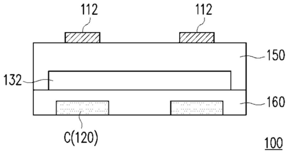
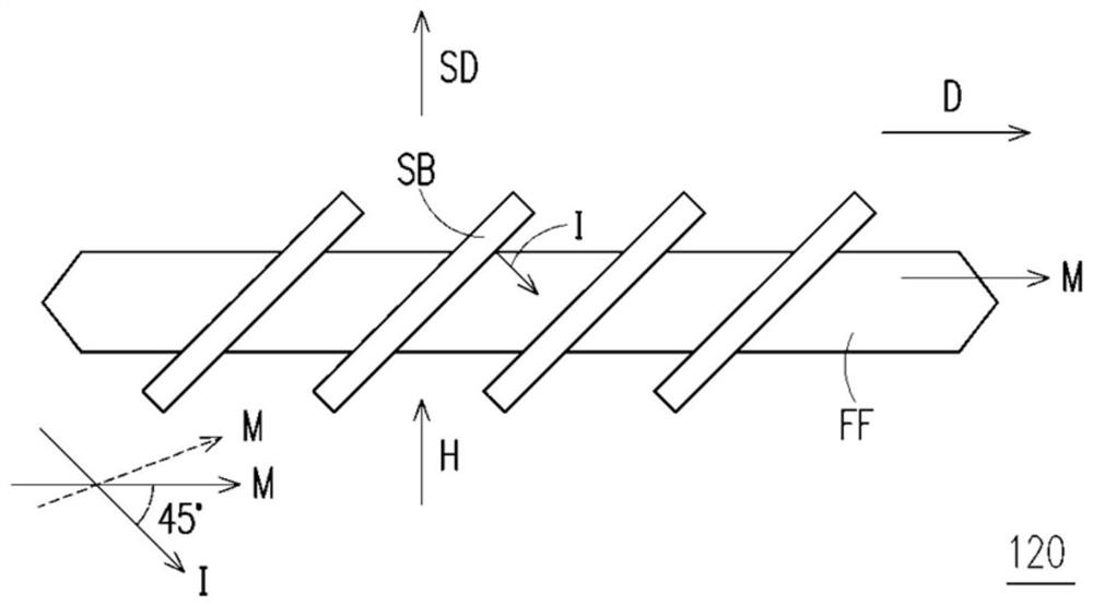
[0058] figure 1 It is a schematic top view of a magnetic field sensing device according to an embodiment of the present invention. figure 2 for figure 1 A schematic cross-sectional view of section A-A' in . Figure 3A and Figure 3B for figure 1 Different layout methods for anisotropic magnetoresistive sensors.

[0059] Please r...


PUM


Abstract

The invention provides a magnetic field sensing device. The magnetic field sensing device comprises a plurality of magnetoresistive sensors, a detection magnetic field generating element, a pluralityof magnetic field direction setting elements and a current generator, each magnetoresistive sensor is provided with a long axis and a short axis which are perpendicular to each other. The current generator is used for selectively applying a first current to the detection magnetic field generation element, so that the detection magnetic field generation element generates a reference magnetic fieldfor the magnetoresistive sensors. The magnetic field direction of the reference magnetic field is parallel to the minor axis. The current generator is used for selectively applying a second current toenable the magnetic field direction setting elements to generate a plurality of set magnetic fields for the magnetoresistive sensors. The magnetic field direction of each set magnetic field is parallel to the long axis.

Description

technical field [0001] The invention relates to a magnetic field sensing device, in particular to a magnetic field sensing device with a self-built detecting magnetic field generating element. Background technique [0002] With the development of science and technology, electronic products with navigation and positioning functions are becoming more and more diversified. Electronic compasses provide functions equivalent to traditional compasses in the fields of car navigation, aviation and personal handheld devices. In order to realize the function of the electronic compass, the magnetic field sensing device becomes a necessary electronic component. [0003] When the magnetic field sensing device is completed, it is usually sent to the inspection system for calibration. However, in order to generate a large-scale detection magnetic field to detect multiple magnetic field devices at one time, the detection system requires a large volume and requires a large current. In addi...

Claims


Application Information

Patent Timeline
Patent Type & Authority Applications(China)
IPC IPC(8): G01R33/09
CPCG01R33/096G01R33/091
Inventor 袁辅德
Owner ISENTEK INC
Why Eureka
Try Eureka