High-speed motor cooling system

A technology for cooling systems and high-speed motors, applied in cooling/ventilation devices, electromechanical devices, electrical components, etc., can solve problems that affect the normal use of motors, affect work efficiency, and have inconspicuous effects, achieve low loss, prolong service life, The effect of reducing dosage

Pending Publication Date: 2019-11-19
NANJING NORMAL UNIVERSITY
View PDF10 Cites 7 Cited by
  • Summary
  • Abstract
  • Description
  • Claims
  • Application Information

AI Technical Summary

Problems solved by technology

[0004] In the process of realizing the present invention, the inventor found that the prior art has at least the following problems: First, the small holes on the motor always connect the inside of the motor with the outside world, which will cause dust to enter the inside of the motor through the small holes, causing the inside of the motor to be full of dust , thereby affecting the normal use of the motor; secondly, the heat dissipation of the motor is only carried out through the small holes on the casing, and there are problems such as slow heat dissipation, low efficiency, long time consumption and ineffective effects; Cause forced downtime, thus affecting actual work efficiency; thus causing unnecessary trouble due to forced downtime

Method used


Image

  • High-speed motor cooling system
  • High-speed motor cooling system
  • High-speed motor cooling system

Examples


Embodiment Construction

[0025] In order to make the object, technical solution and advantages of the present invention clearer, the implementation manner of the present invention will be further described in detail below in conjunction with the accompanying drawings.

[0026] It should be noted that when a component is said to be "fixed" to another component, it can be directly on the other component or there can also be an intervening component. When a component is said to be "connected" to another component, it may be directly connected to the other component or there may be intervening components at the same time. When a component is said to be "set on" another component, it may be set directly on the other component, or there may be an intervening component at the same time. The terms "disposed with", "connected" and similar expressions used in the present invention are for the purpose of illustration only.

[0027] Unless otherwise defined, all technical and scientific terms used in the present...


PUM


Abstract

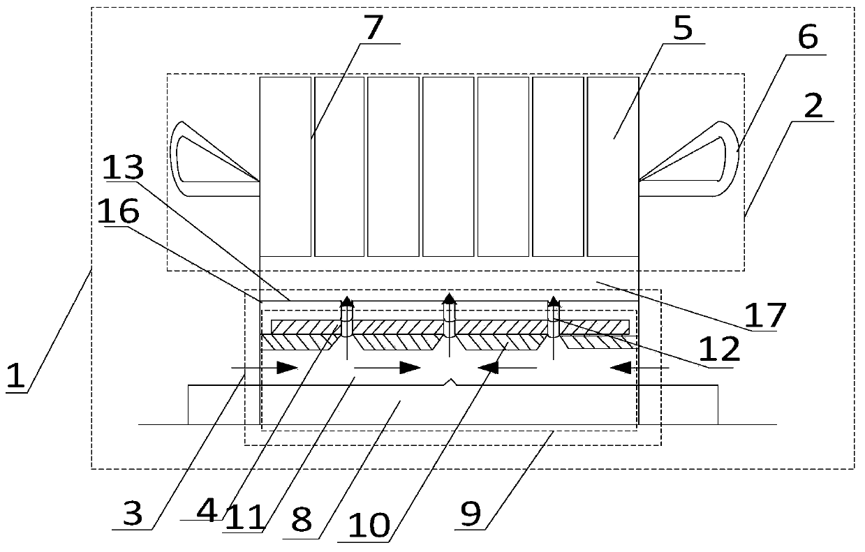
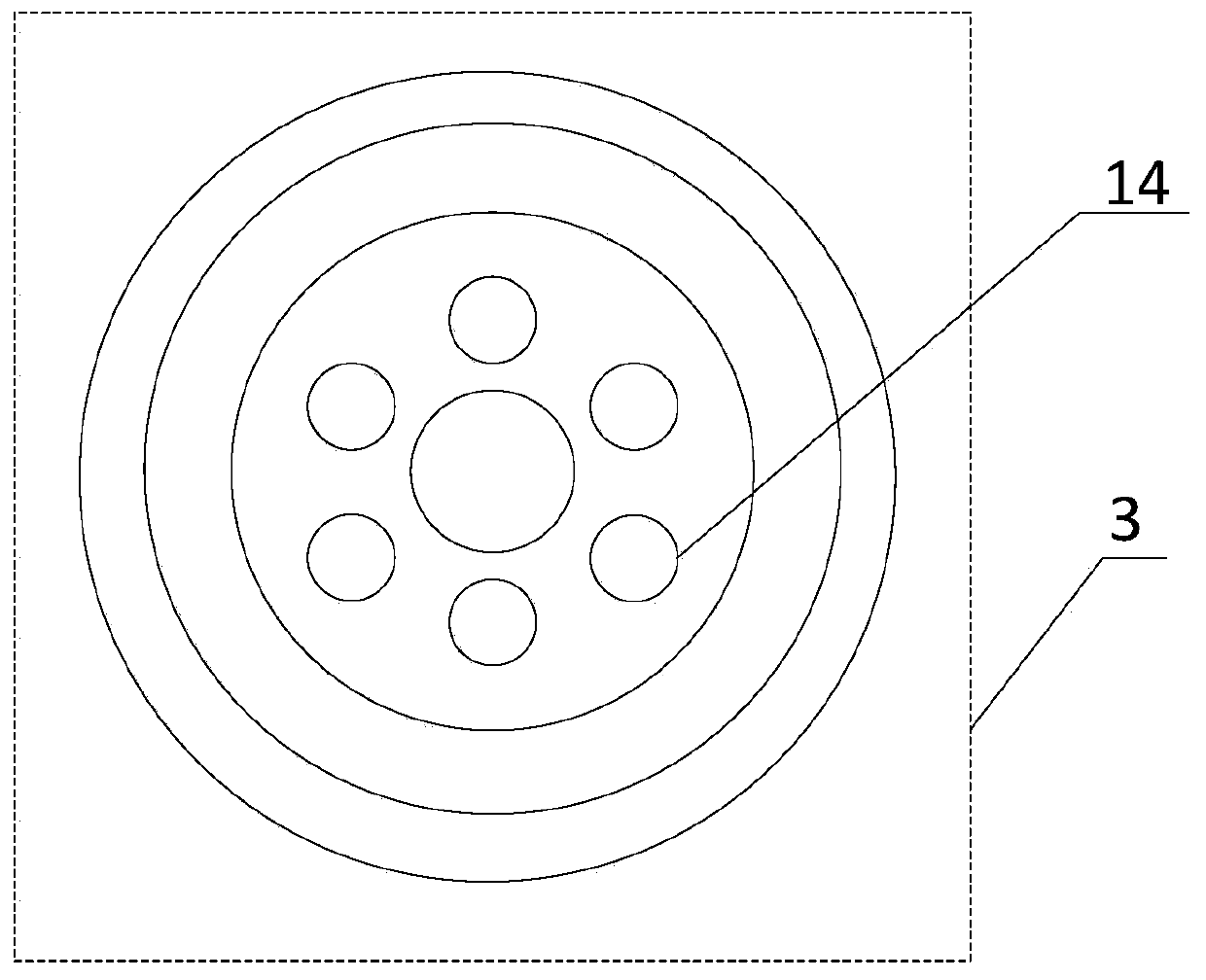
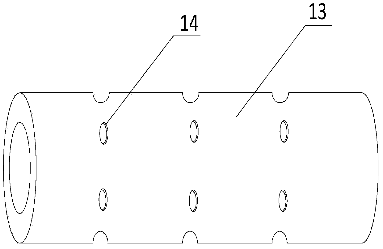
The invention discloses a high-speed motor cooling system. The system comprises a motor, and the motor comprises a stator, a rotor and permanent magnets. The stator comprises stator cores, stator windings and stator core radial ventilating ducts; the stator windings are wound on the stator cores; the stator core radial ventilating ducts are located between the stator cores; the rotor comprises a rotating shaft and a rotor core, the rotating shaft is fixed in the middle of the rotor core, grooves are formed in the surface of the rotor core, and a rotor core axial ventilation hole and rotor ironcore radial ventilation holes which communicate with each other are formed in the rotor core. The permanent magnets are attached to the interiors of the grooves of the rotor core, and the permanent magnets are sleeved with sheaths. According to the invention, the motor is cooled through the ventilating ducts communicating between the stator and the rotor; and the independent cold air supply device and the centrifugal fan are used for cooling the motor and can be used for cooling the motor at the same time, so that the cooling effect of the motor is more obvious.

Description

technical field [0001] The invention relates to the field of motor cooling, in particular to a high-speed motor cooling system. Background technique [0002] With the rapid development of the world, the heavy industry is also developing towards high speed, high efficiency, low energy consumption and high automation. Among them, the technical improvement and structural innovation of high-speed motors are becoming more and more urgent. Due to the high heating power of high-speed permanent magnet motors, it is easy to cause the temperature of the stator and rotor to be too high, thereby affecting the efficiency of the motor, and may even cause the motor to be scrapped. Therefore, the cooling direction of the motor rotor has become an important research goal in the development of motor technology. [0003] In the prior art, the heat dissipation of the motor is usually to open some small holes on the casing. When the motor is working, the outside air enters the interior of the mo...

Claims


Application Information

Patent Timeline
Patent Type & Authority Applications(China)
IPC IPC(8): H02K9/10H02K9/04H02K1/20H02K1/32H02K7/00H02K1/27
CPCH02K9/10H02K9/04H02K1/20H02K1/32H02K7/003H02K1/2706
Inventor 丁树业李政辉王影
Owner NANJING NORMAL UNIVERSITY
Why Eureka
Try Eureka