
Internal combustion locomotive electric transmission system and auxiliary filtering cabinet thereof

A technology for auxiliary filter cabinets and diesel locomotives, which is applied in the direction of locomotives, electrical components, and structural parts of electrical equipment. It can solve the problems of limited installation space for auxiliary filter cabinets, and achieve high cost, high utilization, and reasonable layout. Effect

Active Publication Date: 2019-11-22
CRRC YONGJI ELECTRIC CO LTD
View PDF7 Cites 0 Cited by
  • Summary
  • Abstract
  • Description
  • Claims
  • Application Information

AI Technical Summary

Problems solved by technology

[0005] The invention solves the problem that the auxiliary filter cabinet of the existing diesel locomotive needs to be redesigned due to the change of the installation position and the limited installation space, and the structure of the auxiliary filter cabinet and the selection of internal parts, and provides an electric transmission system of the diesel locomotive and its auxiliary filter cabinet. filter cabinet

Method used


Image

  • Internal combustion locomotive electric transmission system and auxiliary filtering cabinet thereof
  • Internal combustion locomotive electric transmission system and auxiliary filtering cabinet thereof
  • Internal combustion locomotive electric transmission system and auxiliary filtering cabinet thereof

Examples


Embodiment Construction

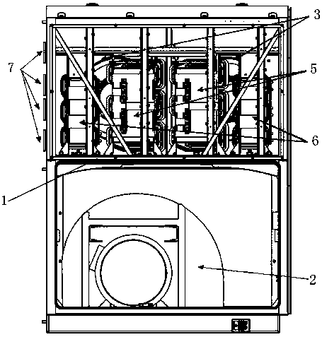
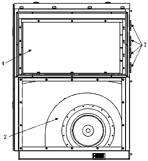
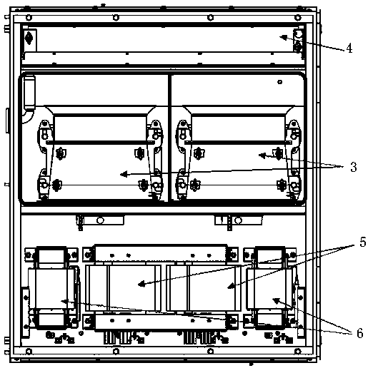
[0019] Diesel locomotive electric transmission system includes traction auxiliary converter, auxiliary filter, traction auxiliary converter cabinet, and auxiliary filter cabinet; the bottom of the auxiliary filter cabinet is open, and a partition 1 is provided in the middle of the inner cavity to separate the inner cavity of the auxiliary filter cabinet. Divided into an upper cavity and a lower cavity, the auxiliary filter cabinet is placed on the front frame fan 2 on the diesel locomotive through the bottom open mouth, the fan 3 and the radiator 4 for the water cooling system of the traction auxiliary converter, the transformer 5 and the reactor of the auxiliary filter 6 is set in the upper cavity of the auxiliary filter cabinet, and the filter capacitor, contactor and circuit breaker of the auxiliary filter are set in the traction auxiliary converter cabinet; the water cooling interface 7 of the radiator 4 for the traction auxiliary converter water cooling system leads to the ...


PUM


Abstract

The invention relates to an internal combustion locomotive electric transmission system, in particular to an internal combustion locomotive electric transmission system and an auxiliary filter cabinetthereof. The problem that due to the facts that the installation position of an auxiliary filtering cabinet of an existing internal combustion locomotive is changed and the installation space is limited, the structure of the auxiliary filtering cabinet and selection of internal parts need to be redesigned is solved. In the process of redesigning the auxiliary filter cabinet, comprehensive consideration is creatively performed on functions and structures of the auxiliary filter cabinet and a traction auxiliary converter, and overall component arrangement is performed. A cooling system of the converter is placed in the auxiliary filtering cabinet through a fan and a radiator. A filter capacitor, a contactor and a circuit breaker of the auxiliary filter are arranged in the traction auxiliaryconverter cabinet, so space occupation of large components in the converter cabinet is reduced, the layout of the converter is more reasonable, forced air cooling is carried out on the transformer and the reactor of the auxiliary filter by means of the cooling fan of the converter, and self-cooling is changed into air cooling in model selection design of the transformer and the reactor.

Description

technical field [0001] The invention relates to an electric transmission system of a diesel locomotive, in particular to an electric transmission system of an internal combustion locomotive and an auxiliary filter cabinet thereof. Background technique [0002] The electric transmission system of a high-power diesel locomotive includes a traction auxiliary converter, an auxiliary filter, etc. The traction auxiliary converter is located in the traction auxiliary converter cabinet, and the auxiliary filter is located in the auxiliary filter cabinet. The function of the auxiliary filter is to filter the three-phase power output from the auxiliary converter and provide high-quality power to the auxiliary system of the locomotive. [0003] The existing locomotive auxiliary filter cabinet generally includes transformers, reactors, filter capacitors, contactors and circuit breakers, etc., and there are also fans for cooling the transformers and reactors, which are matched with the a...

Claims


Application Information

Patent Timeline
Patent Type & Authority Applications(China)
IPC IPC(8): B61C17/00H02M1/00H05K7/20
CPCB61C17/00H02M1/00H05K7/20172H05K7/20181H05K7/20218H05K7/20272
Inventor 马连凤刘谆李晓莉孙湘漪孙晓丽朱云鹏田鹏刚
Owner CRRC YONGJI ELECTRIC CO LTD
Learn More