Bottle bottom separating device of vertical tube type bottle making machine

A technology for separating devices and controlling bottles, which is applied in the direction of manufacturing tools, glass manufacturing equipment, glass reshaping, etc. It can solve problems such as reducing product qualification rate and yield, increasing production and maintenance costs of enterprises, and damage to the surface of processed bottles. , to achieve the effect of improving the work efficiency of the enterprise, reducing the labor force and labor intensity, and reducing the daily maintenance work

Pending Publication Date: 2019-11-22
SHIJIAZHUANG LOYAL MACHINERY MFG
View PDF0 Cites 1 Cited by
  • Summary
  • Abstract
  • Description
  • Claims
  • Application Information

AI Technical Summary

Problems solved by technology

If the bottle has a slanted bottom, the highest point will exceed the length of the bottle body, and the lowest point will be shorter than the length of the bottle body. Such bottles will become waste products or unqualified products will be kicked out, thereby reducing the product qualification rate and increasing the production cost of the enterprise.
[0006] The second is to cause surface damage to the processed bottle
On the one hand, since the collet claws and the bottle drop tube are always rotating when the manipulator picks up the bottle, it will cause friction between the manipulator and the bottle when the manipulator picks up the bottle, thus causing damage to the bottle surface
On the other hand, after the surface of the collet claws is worn, the force of each collet claw of the collet claws to clamp the bottle body is uneven, which is easy to cause damage to the surface of the bottle body by the collet claws, which greatly reduces the production quality of the product. , reduce product pass rate and finished product rate, increase production cost of enterprises
[0007] The third is to increase the production and maintenance costs of enterprises
This method requires a certain amount of manpower for maintenance, which is not only time-consuming and labor-intensive, but also affects production efficiency, consumes energy, and greatly increases the production cost of the enterprise.

Method used


Image

  • Bottle bottom separating device of vertical tube type bottle making machine
  • Bottle bottom separating device of vertical tube type bottle making machine
  • Bottle bottom separating device of vertical tube type bottle making machine

Examples


Embodiment

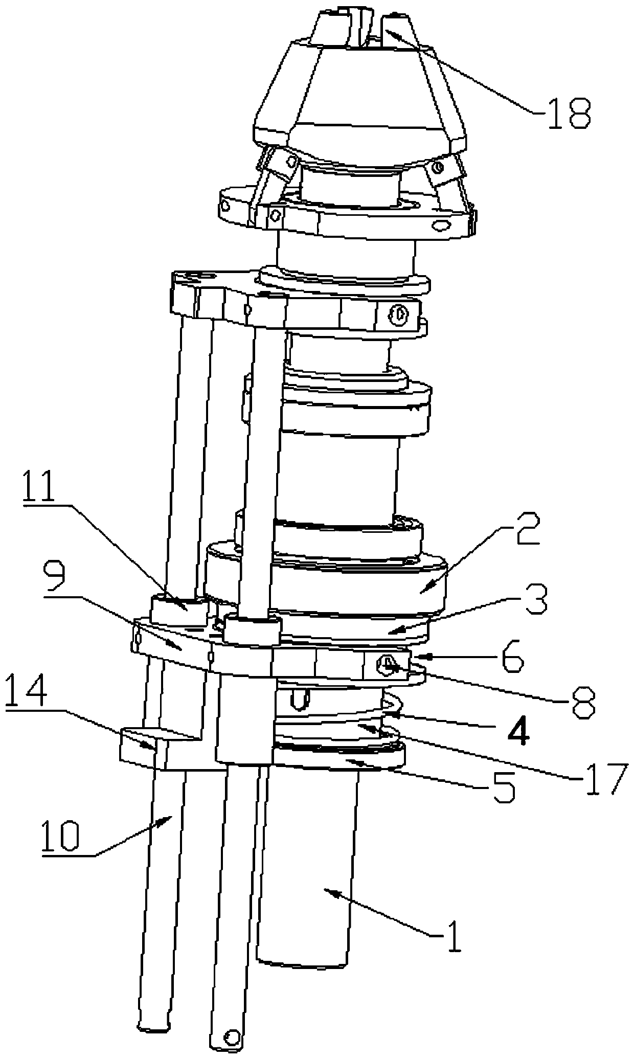
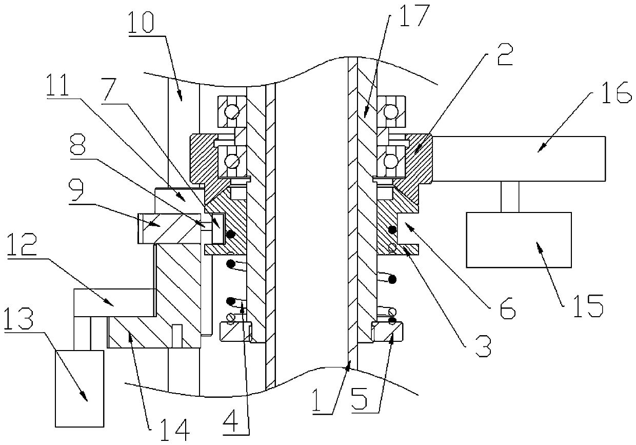
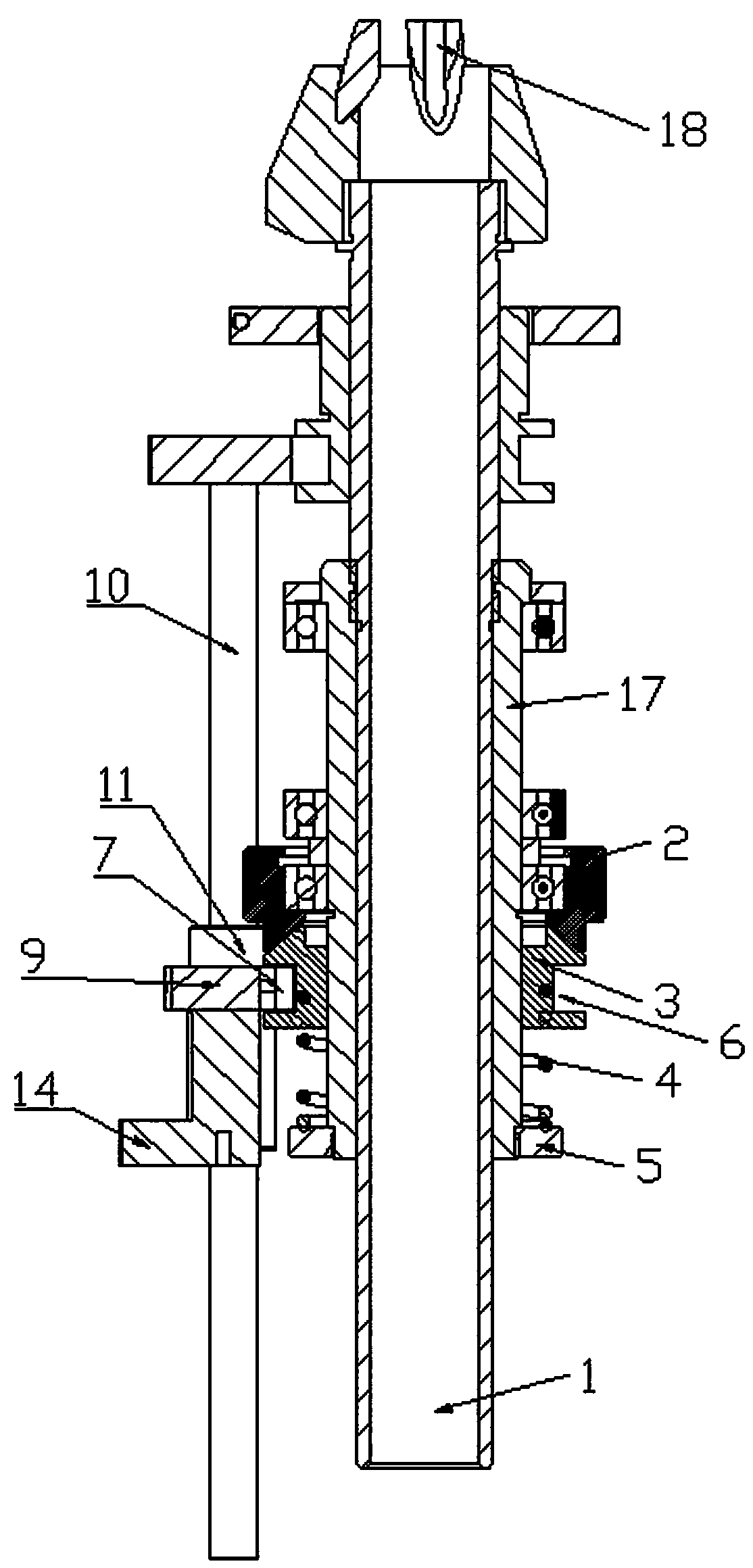
[0032] Example A bottle bottom separation device for vertical control bottle mechanism

[0033] In this embodiment, during normal bottle production, the reset mechanism drives the upper clutch 2 to contact the lower clutch 3, so that the chuck jaw 18 is driven by power to rotate; when the robot picks up the bottle, the upper clutch 2 and the lower clutch 3 are driven by the driving mechanism Phase separation makes chuck jaw 18 stop rotating.

[0034] Such as Figure 1 to Figure 3 As shown, this embodiment includes a bottle drop tube 1 with a bottle tube inside. The bottle drop tube 1 is in the shape of a round tube. The upper part of the bottle drop tube 1 is fixed with a chuck assembly, and the lower part of the bottle drop tube 1 is connected with an outer sliding sleeve through a sliding key. 17.

[0035] 1. Chuck components

[0036] The collet assembly is fixed on the collet assembly on the bottle drop tube 1 top. The collet assembly adopts the collet assembly on the b...


PUM

PropertyMeasurementUnit
diameteraaaaaaaaaa
perimeteraaaaaaaaaa

Abstract

The invention discloses a bottle bottom separating device of a vertical tube type bottle making machine. The device further comprises clutches, a power mechanism and a driving mechanism, wherein the clutches comprise an upper clutch and a lower clutch which both sleeve the lower part of a bottle falling tube; the upper clutch is connected with a bottle falling pipe bearing, and the upper clutch isconnected with a power mechanism of the bottle making machine for driving the upper clutch to rotate; and the lower clutch is movably connected with the bottle falling pipe and is connected with thecontrol end of the driving mechanism for controlling the clutch to be opened and closed. When a manipulator takes a bottle, chuck jaws stop in a static state. The separating device is suitable for thevertical tube bottle making machine and is used for making the bottle bottom.

Description

technical field [0001] The invention belongs to the technical field of a vertical tube bottle machine, in particular to a bottle bottom separation device for a vertical tube tube machine. Background technique [0002] At present, the control operation methods of the vertical control bottle machine for the clamping and fixing device and the unloading station of the bottom of the processed glass bottle are mainly as follows: [0003] In the clamping and fixing device of the bottom of the vertical control bottle mechanism, the upper end of the bottle-making tube is fixed with the chuck claw of the chuck assembly, and the chuck claw is connected with the other parts in the chuck assembly to control the chuck claw. Hold the bottle. In the normal production of the bottle base, driven by the power mechanism, the drop tube and chuck claws are always in a rotating state to complete the process of making the bottom. [0004] The second control operation method of the vertical contro...

Claims


Application Information

Patent Timeline
Patent Type & Authority Applications(China)
IPC IPC(8): C03B23/045
CPCC03B23/045
Inventor 张田刘新玺
Owner SHIJIAZHUANG LOYAL MACHINERY MFG
Why Eureka
Try Eureka