
Ultra-high accuracy temperature measurement method

A precision measurement, ultra-high technology, applied in thermometers, measuring devices, heat measurement, etc., can solve the problem that the accuracy and resolution cannot be improved beyond the ultra-high index, product consistency is not high, open-loop control technology uncertainty drift, etc. problem, to achieve the effect of improving accuracy and resolution and realizing ultra-high precision measurement

Active Publication Date: 2019-11-22
叶志刚
View PDF14 Cites 0 Cited by
  • Summary
  • Abstract
  • Description
  • Claims
  • Application Information

AI Technical Summary

Problems solved by technology

The traditional temperature measuring instrument uses a temperature sensor plus an operational amplifier, A / D conversion, reference voltage module and CPU processor, etc. Due to the influence of temperature drift, device drift factors and nonlinear factors of the device or circuit, the temperature measuring instrument It is difficult to achieve ultra-high indicators such as precision and resolution, and the consistency of the products produced is not high
Although the lock-in amplifier measurement technology is now used in the temperature measuring instrument, its accuracy and resolution have been greatly improved, but the lock-in amplifier uses the open-loop phase-locked phase detection technology to measure the temperature signal, which is still affected by nonlinearity, temperature Drift, sudden interference and uncertainty drift of open-loop control technology, resulting in the improvement of accuracy and resolution is still less than the goal of ultra-high indicators

Method used


Image

  • Ultra-high accuracy temperature measurement method
  • Ultra-high accuracy temperature measurement method

Examples


Embodiment Construction

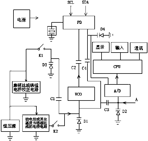
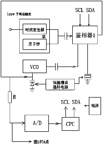
[0015] Such as figure 1 As shown, the temperature measuring instrument is based on temperature sensor, VCO and varactor diodes D1~D4, phase detector PD, A / D analog-to-digital converter, processor CPU, and can also include correction circuit, constant voltage source, relative Measurement circuits and peripheral circuits of processors. The working process is as follows: first, through the bridge circuit composed of platinum resistance or other temperature sensing heads and constant voltage sources, the temperature signal reflected by the temperature sensing head is converted into a certain millivolt level voltage signal through the switch K 2 Added to the varactor D 1 On, and converted into a certain value of capacitance F1, this capacitance F1 at the same time through the capacitance C 3 Connect the varactor diode D 2 The fitting capacitance value F2, and then through the capacitance C 1 Connect the varactor diode D 3 Form the fitting capacitance value F3, the phase-lockin...


PUM


Abstract

The invention discloses an ultra-high accuracy temperature measurement method. A bridge circuit composed of a temperature sensor and a constant voltage source converts a temperature signal into a fitting capacitance value F1. The phase-locked voltage PDV1 of the PD phase detector unit is applied to a variable capacitance diode to form the fitting capacitance value F4. All the fitting capacitance values form a total fitting capacitance value F in series and parallel. The fitting capacitance value F is connected to a VCO unit and added to a PD phase detector unit by a capacitor C2 to act as oneof the frequency signals to be compared and compared with the other path of frequency signal arranged in a reference crystal oscillator and CPU, SCL and SDA communication lines and finally a stable phase-locked voltage PDV1 is generated. The difference between PDV1 and the base voltage PDV0 is the measured value of PDV. The measured value is sent to the CPU for processing and converted into a realtemperature value for display or communication. The problems of non-linearity, temperature drift, sudden interference and uncertain drift of open loop control technology can be solved and ultra-highaccuracy temperature measurement can be realized.

Description

technical field [0001] The invention relates to a temperature measurement method, in particular to an ultra-high precision temperature measurement method. Background technique [0002] Temperature measurement, especially ultra-high-precision temperature measurement technology, has a wide range of applications in the fields of measuring instruments, industrial control, medical instruments, and deep space exploration. Regardless of the application in the embedding of the product itself, or in the calibration and calibration of the product's R&D and manufacturing process in terms of accuracy, resolution, and repeatability, temperature measuring instruments play an important role. The traditional temperature measuring instrument uses a temperature sensor plus an operational amplifier, A / D conversion, reference voltage module and CPU processor, etc. Due to the influence of temperature drift, device drift factors and nonlinear factors of the device or circuit, the temperature meas...

Claims


Application Information

Patent Timeline
Patent Type & Authority Applications(China)
IPC IPC(8): G01K7/18
CPCG01K7/18
Inventor 叶志刚
Owner 叶志刚
Learn More