Micro-nano tube clamping device and micro-nano gas-liquid flow experiment device and method

A micro-nano tube and clamping device technology, which is applied in the field of petroleum exploration, can solve the problems of poor pressure resistance, poor flexibility, easy to break and break, etc. High pressure resistance, breaking and shattering resistance

Pending Publication Date: 2019-11-22
SOUTHWEST PETROLEUM UNIV
View PDF1 Cites 4 Cited by
  • Summary
  • Abstract
  • Description
  • Claims
  • Application Information

AI Technical Summary

Problems solved by technology

[0005] However, the current microscopic experiments on microtubules have the following problems: 1) Due to the small size of microtubules, poor flexibility and low strength, they are not easy to be clamped, easily broken and broken during the experiment; 2) It is difficult to carry out the experiment under high pressure difference (>35MPa) , the microtube clamping device has poor pressure resistance; 3) the microtube clamping seal is poor, resulting in inaccurate experimental results; 4) the clamping device has poor flexibility and cannot flexibly support the change of pipe diameter

Method used


Image

  • Micro-nano tube clamping device and micro-nano gas-liquid flow experiment device and method
  • Micro-nano tube clamping device and micro-nano gas-liquid flow experiment device and method

Examples


Embodiment 1

[0079] Embodiment 1 Gas micro-nanotube experiment

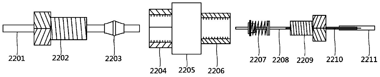
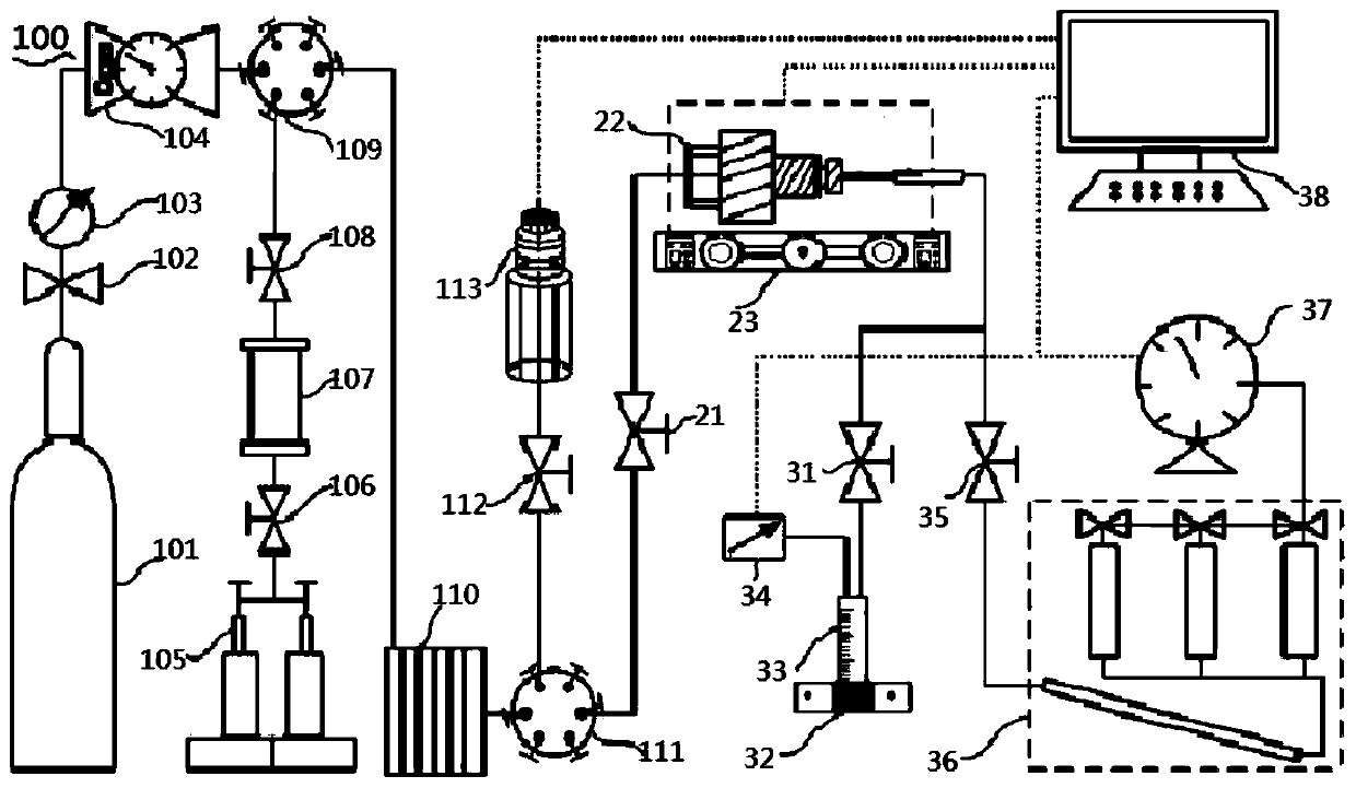
[0080] S1. Close all valves and switches, select a micro-nanotube 2210 with a predetermined inner diameter and length, clamp it on the micro-nanotube clamping device 22, and adjust the temperature of the constant temperature system 23 to a predetermined temperature;

[0081] S2. After the temperature of the constant temperature system 23 is constant, open the first switch 102, the fourth switch 112, the fifth switch 21, and the seventh switch 35;

[0082] S3, open the decompression valve 104 to set the predetermined gas pressure, record the reading of the wet gas flowmeter 37 and the experiment time;

[0083] S4, adjust the pressure reducing valve 104 to change the experimental pressure, repeat step S3, until the required number of experimental groups;

[0084] S5. After the experiment is over, close the first switch 102, and close the decompression valve 104 after releasing the pressure to 0, and remove the micro-nanotube c...

Embodiment 2

[0085] Embodiment 2 liquid micro-nanotube experiment

[0086] S1. Close all valves and switches, select a micro-nanotube 2210 with a predetermined inner diameter and length, clamp it on the micro-nanotube clamping device 22, and adjust the temperature of the constant temperature system 23 to a predetermined temperature;

[0087] S2. After the temperature of the constant temperature system is constant, first turn on the second switch 106, the third switch 108, the fifth switch 21, and the sixth switch 31, and finally turn on the ISCO pump 105;

[0088] S3, adjust the ISCO pump 105 to set a predetermined pressure, record the volume of the liquid in the measuring cylinder 33 and the experiment time;

[0089] S4, adjust the ISCO pump 105 to change the pressure, repeat step S3, until the required number of experimental groups;

[0090] S5. Turn off the ISCO pump 105 after the experiment, release the pressure to 0, and remove the micro-nanotube clamping device 22 .

[0091] Wherei...


PUM

PropertyMeasurementUnit
lengthaaaaaaaaaa
lengthaaaaaaaaaa
lengthaaaaaaaaaa

Abstract

The invention provides a micro-nano tube clamping device, and a micro-nano gas-liquid flow experiment device and method. The micro-nano tube clamping device comprises a routine experiment pipeline, anupstream hollow sealing bolt, a sealing ring, an upstream sealing cavity, a fluid buffer cavity, a downstream sealing cavity, a mechanical compaction sealing lantern ring, a high-pressure-resistant micro-nano tube butt joint sleeve, a downstream hollow sealing bolt, a micro-nano tube and a sealing sleeve. The micro-nano tube clamping device is outstanding in high-pressure resistance and sealing performance, and seamless butt joint between a conventional seepage experiment and a micro-nano experiment can be achieved; and the micro-nano tube clamping device is arranged in the micro-nano gas-liquid flow experiment device, the high-pressure condition of a real stratum can be simulated, and the micro-nano scale gas-liquid phase flow experiment can reflect the nonlinear seepage mechanism of thereal stratum more accurately.

Description

technical field [0001] The invention relates to the technical field of petroleum exploration, in particular to a micro-nano tube clamping device, a micro-nano gas-liquid flow experiment device and a method. Background technique [0002] With the steady growth of my country's economy, the demand for oil continues to increase. Due to the lack of reserve oil reserves in medium and high permeability reservoirs and the slow development of low permeability oil resources in my country, the contradiction between oil supply and demand has been intensified, and the oil supply has been heavily dependent on imported oil. In my country's newly proven geological reserves of petroleum and natural gas resources, the resources of low-permeability tight reservoirs occupy an absolute proportion. The efficient development of low-permeability oil and gas resources is of great significance to ensure my country's energy security. Obviously different from high-permeability reservoirs, the seepage...

Claims


Application Information

Patent Timeline
Patent Type & Authority Applications(China)
IPC IPC(8): G01N15/08G01M10/00
CPCG01M10/00G01N15/0806G01N15/0826
Inventor 梁彬王东李闽吴倩曹江娜
Owner SOUTHWEST PETROLEUM UNIV
Why Eureka
Try Eureka