High-precision multifunctional chip mounter and using method thereof

A multi-functional, chip loader technology, applied in the direction of conveyor objects, transportation and packaging, electrical components, etc., can solve the problems of slow speed, high operator requirements, complex structure, etc.

Pending Publication Date: 2019-11-22
恩纳基智能科技无锡有限公司
View PDF0 Cites 7 Cited by
  • Summary
  • Abstract
  • Description
  • Claims
  • Application Information

AI Technical Summary

Problems solved by technology

[0002] In the case that the chip loading machine in the prior art can achieve ±7 micron precision and can paste up to 6 kinds of chips, the speed is often not fast enough, and the UPH (capacity per hour) is about 400 to 500
However, the placement machine with a UPH of 1500 can only reach ±10 microns, and can only mount a single chip.
However, the placement machine that can satisfy the accuracy, speed, and number of chips that can be mounted, due to the poor integration of functions, makes the volume of the machine reach 2.2m in length x 1.8m in width x 2.3m in height

Method used


Image

  • High-precision multifunctional chip mounter and using method thereof
  • High-precision multifunctional chip mounter and using method thereof
  • High-precision multifunctional chip mounter and using method thereof

Examples


Embodiment 1

[0160] Embodiment 1: Take a chip pasted as an example for illustration

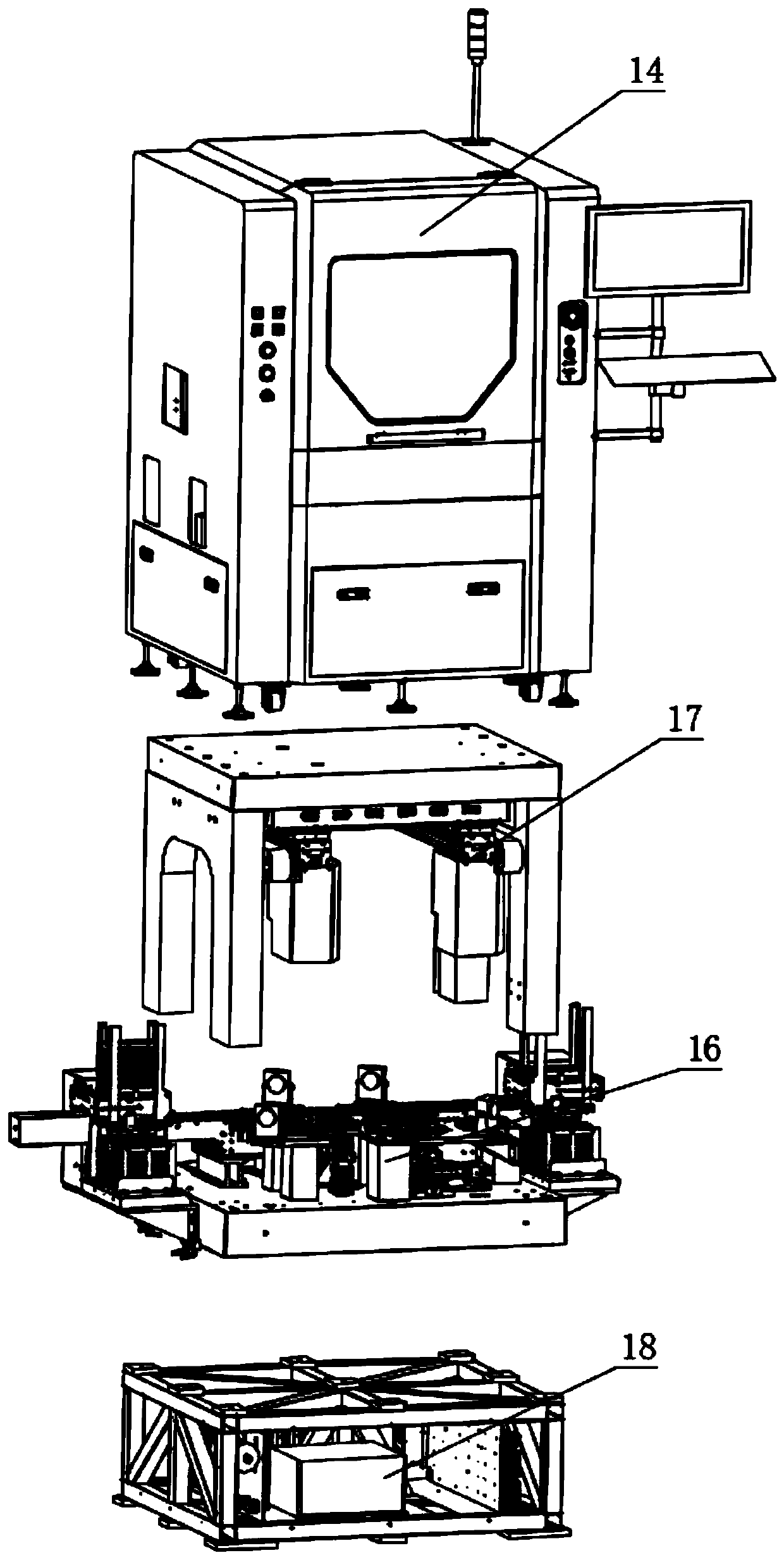
[0161] Manually install the same suction nozzle 17443 and glue dipping needle 174614 on the suction nozzle assembly 1744 and the glue dipping assembly 1746 of the two welding head mechanisms 1704; In the sheet feeding mechanism 2; place two empty sheet material boxes at the same position of the unloading mechanism 3; same as the above step 3, place the jig 57 with the chip magazine 58 on the jig base of station one seat 52;

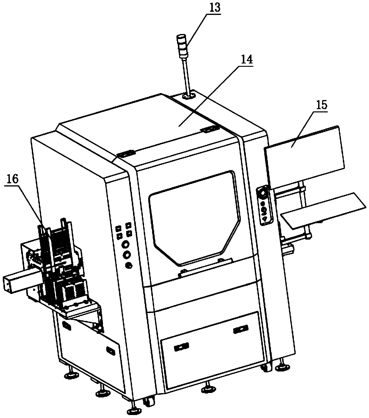
[0162] Through the display screen 15 to start the program, the pushing system 203 pushes the tablet from the tablet magazine onto the rail conveying mechanism 12, and transports it forward along the track; when the first tablet is delivered to the middle track assembly 1205, The ejecting mechanism ejects and fixes the tablet 19, and when the second tablet is delivered to the front track assembly 1206, it is also fixed by the same ejecting mechanism;

[0163] Repeat the above step s...

Embodiment 2

[0166] Embodiment 2: Take two kinds of chips as an example for illustration.

[0167] The difference from Embodiment 1 is that different suction nozzles 17443 and different glue dipping needles 174614 are manually installed on the suction nozzle assembly 1744 and the glue dipping assembly 1746 of the two welding head mechanisms 1704, and the station one and station two respectively Place different chips.

Embodiment 3

[0168] Embodiment 3: take three types of chips as an example for illustration.

[0169] The difference with Embodiment 1 is:

[0170] Manually install different suction nozzles 17443 and different glue dipping needles 174614 on the suction nozzle assembly 1744 and the glue dipping assembly 1746 of the two welding head mechanisms 1704;

[0171] Manually place the suction nozzle 17443 and the glue-dipping needle 174614 that will be used in the process on the quick-change mechanism 8;

[0172] Manually place different chips into station 1 and station 2 according to assembly requirements;

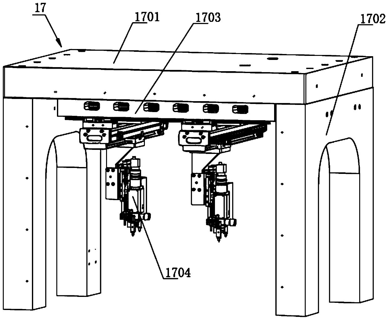
[0173] Carry out the chip mounting action with the above steps; when it is necessary to replace the suction nozzle 17443 or the glue dipping needle 174614, the welding head mechanism 1704 moves to the quick change mechanism 8 under the drive of the linear motion component 1703, and the suction nozzle component 1744 Hang the suction nozzle 17443 and the glue dipping needle 174614 on the glue dip...


PUM


Abstract

The invention discloses a high-precision multifunctional chip mounter and a using method thereof. The multifunctional chip mounter comprises a shell, a control device is installed at the bottom in the shell, a multifunctional chip picking and placing device is installed above the control device, a multifunctional double-station welding head mechanism is installed above the multifunctional chip picking and placing device in a matched mode, and the multifunctional double-station welding head mechanism is installed at the top in the shell. The mounter is compact and reasonable in structure, andconvenient in operation, through the mutual cooperation of the functional chip picking and placing device, the multifunctional double-station welding head mechanism, the control device and other mechanisms, the chip mounting work of the chip can be conveniently and automatically completed, the chip mounting precision reaches +/-7 microns, at most eight types of chips can be mounted, the UPH can reach about 1.5 times that of the prior art, the functions are compressed and integrated as much as possible on the basis, the equipment size is small, and the occupied area is small.

Description

technical field [0001] The invention relates to the technical field of chip loading equipment, in particular to a high-precision multifunctional chip loading machine and a method for using the same. Background technique [0002] If the chip loading machine in the prior art can achieve ±7 micron precision and can paste up to 6 kinds of chips, the speed is often not fast enough, and the UPH (production capacity per hour) is about 400 to 500. However, the accuracy of the placement machine with UPH of 1500 can only reach ±10 microns, and it can only mount a single chip. However, the placement machine that can satisfy the accuracy, speed, and number of chips that can be mounted, due to the poor integration of functions, makes the volume of the machine reach 2.2m in length x 1.8m in width x 2.3m in height. The requirements are extremely high (it is a 100-level workshop, and the decoration cost is extremely high), so the chip manufacturer needs the equipment to occupy a small enou...

Claims


Application Information

Patent Timeline
IPC IPC(8): H01L21/67H01L21/677H01L21/683
CPCH01L21/67126H01L21/6838H01L21/67766
Inventor 吴超蒋星
Owner 恩纳基智能科技无锡有限公司
Why Eureka
Try Eureka