Supercharge Your Innovation With Domain-Expert AI Agents!

Method for processing workpiece

A technology for processed objects and processing methods, applied in metal processing equipment, manufacturing tools, laser welding equipment, etc., can solve problems such as wafer defects and cracks, and achieve the effect of suppressing poor processing

Active Publication Date: 2019-11-22
DISCO CORP
View PDF2 Cites 0 Cited by
  • Summary
  • Abstract
  • Description
  • Claims
  • Application Information

AI Technical Summary

Problems solved by technology

[0008] However, when a wafer is processed by the above-mentioned method using a laser processing device, processing defects such as chips and cracks may sometimes occur on the wafer.

Method used


Image

  • Method for processing workpiece
  • Method for processing workpiece
  • Method for processing workpiece

Examples


Embodiment Construction

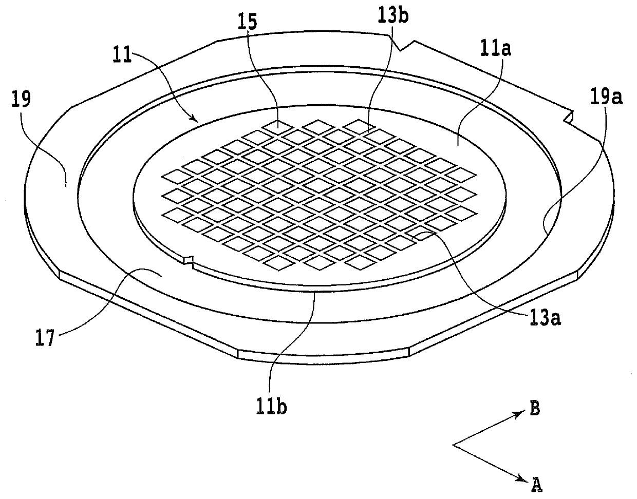
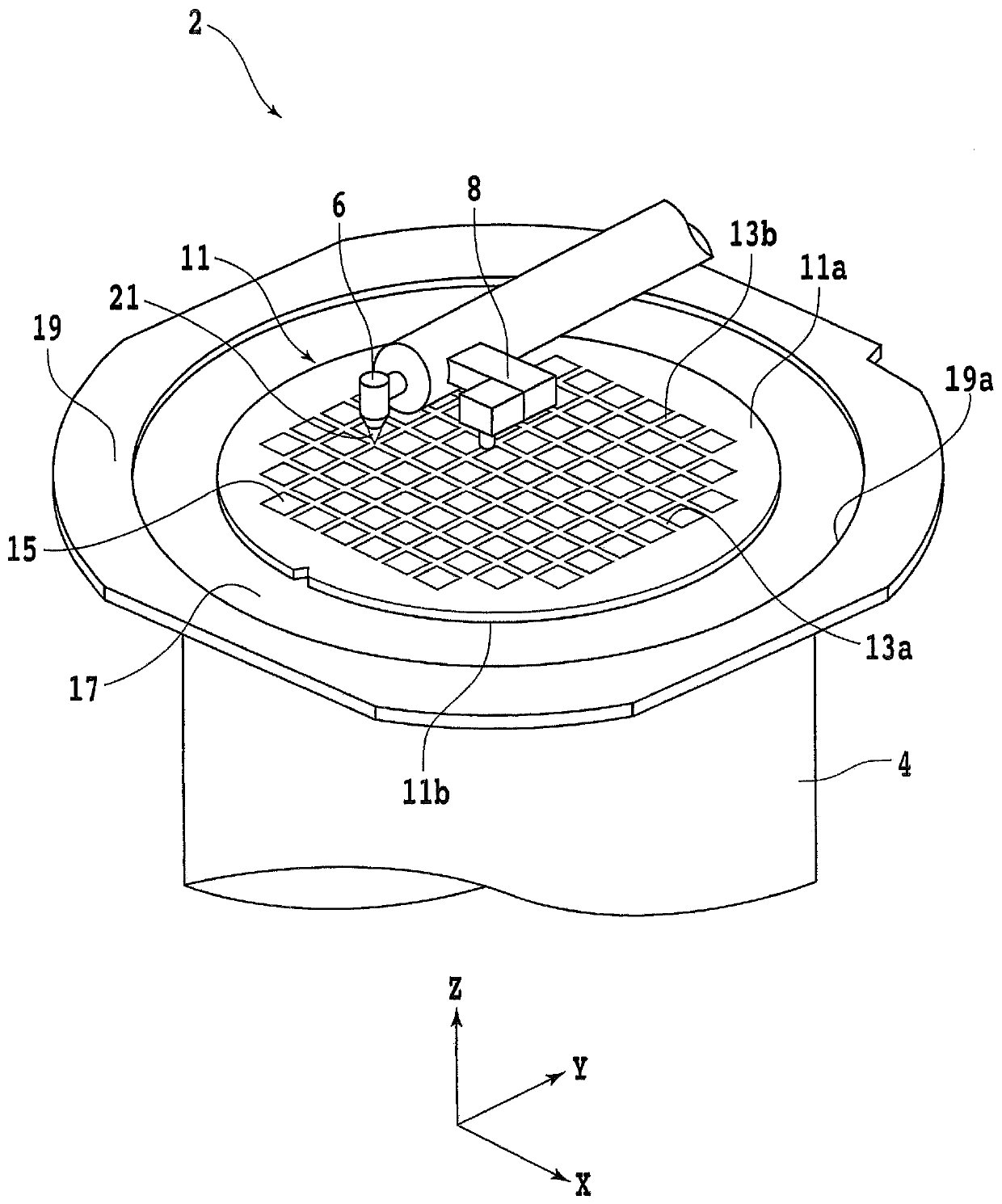
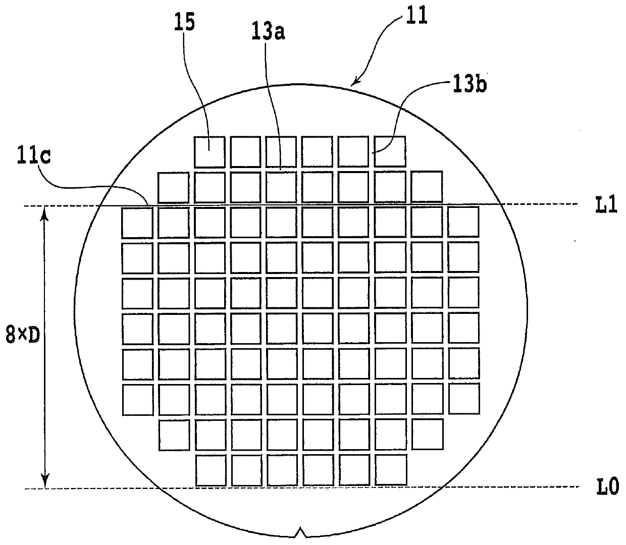
[0022] When irradiating a laser beam to form processing marks such as grooves on a plate-shaped workpiece, for example, when the workpiece is processed sequentially from the end, chipping, cracks, etc. are likely to occur on the workpiece bad. It is presumed that this phenomenon is because: when one of the two regions divided by the processing marks formed by irradiation of laser beams as a boundary is sufficiently small, there will be a gap between the two regions due to irradiation of laser beams. The heat generated during the time produces a large temperature difference.

[0023] That is, it is considered that this problem can be solved if the heat generated during irradiation of the laser beam is conducted in the same manner in the two regions divided by the processing mark as the boundary. Therefore, in the present invention, after forming a plurality of processing marks on the workpiece and dividing them into regions of a certain size, a laser beam is irradiated to a di...


PUM


Abstract

The invention provides a method for processing a workpiece. According to the method, a plate like workpiece is processed by irradiating laser beams on the workpiece, and the generation of defects is prevented during the processing process. According to the processing method, a plate like workpiece with N predetermined cutting lines is processed, wherein N is a natural number greater than 3. The method comprises following steps: step one, irradiating laser beams on a first predetermined cutting line on a first position so as to form a processing mark on the workpiece, wherein the distance between the first position and the outermost predetermined cutting line of the workpiece is 2n*D, D is the distance between two neighbored first predetermined cutting lines and n is a maximal natural number and satisfies 2n<N; and step (k+1), irradiating a predetermined cutting line selected from a first predetermined cutting line on the (k+1)th position so as to form a processing mark on the work piece, wherein the distance between the (k+1)th position and a k-th position is 2n-k*D*m, and m is a natural number.

Description

technical field [0001] The present invention relates to a method of processing a workpiece, which processes a plate-shaped workpiece along a planned dividing line. Background technique [0002] The front surface of the wafer as the base material is divided into a plurality of regions by the planned dividing line called a divider, and devices such as integrated circuits are formed in each region, and then the wafer is divided along the planned dividing line, so that the assembly in the Device chips for various electronic devices. For dividing a wafer, for example, a cutting device that rotates a ring-shaped cutting blade to cut into a target is used. [0003] In cutting processing of a wafer using this cutting device, the wafer is mechanically cut by a rotating cutting blade. Therefore, for example, when the loads acting on the wafer from one side (front) and the other side (back) of the cutting tool vary, machining defects such as chips or cracks tend to occur on the wafer...

Claims


Application Information

Patent Timeline
Patent Type & Authority Applications(China)
IPC IPC(8): H01L21/78B23K26/362
CPCH01L21/78B23K26/362H01L21/76B23K26/38H01L21/67092
Inventor 吉川敏行
Owner DISCO CORP
Features
  • R&D
  • Intellectual Property
  • Life Sciences
  • Materials
  • Tech Scout
  • Unparalleled Data Quality
  • Higher Quality Content
  • 60% Fewer Hallucinations
Learn More