

Pin remover for live replacement of 220kV suspension insulator string
A technology of hanging insulators and live replacement, which is applied in the field of electric power, and can solve the problems of large rebound force of W-shaped spring pins, inability to effectively fix W-shaped spring pins, and unguaranteed success rate.
- Summary
- Abstract
- Description
- Claims
- Application Information
AI Technical Summary
Problems solved by technology
Method used
Image

Examples
Embodiment 1
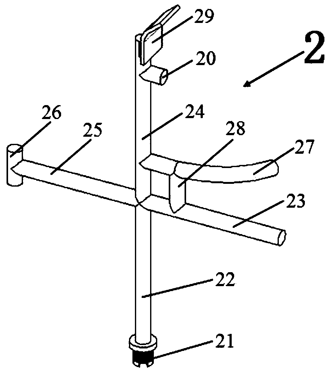
[0033] please see image 3 , a pin remover 2 for live replacement of 220kV suspension insulator strings, which has an anti-collision bar 20, a connecting bolt 21, a main rod 22, a first connecting rod 23, a third connecting rod 24, a second connecting rod 25, a bumper 26, Arc-shaped connecting rod 27, fourth connecting rod 28, wide plate 29; one end of the connecting bolt 21 is fixedly connected with one end of the main rod 22, the outside of the connecting bolt 21 has an external thread, and the other end of the main rod 22 is fixedly connected with one end of the first connecting rod 23 , the other end of the main rod 22 is fixedly connected to one end of the third connecting rod 24, the other end of the main rod 22 is fixedly connected to one end of the second connecting rod 25, the main rod 22 is coaxially arranged with the third connecting rod 24, the first connecting rod 23 is connected to The second connecting rod 25 is coaxially arranged, the first connecting rod 23 an...
Embodiment 2
[0035] please see Figure 4 , a pin remover 2 for live replacement of 220kV suspension insulator strings, which has a connecting bolt 21, a main rod 22, a first connecting rod 23, a third connecting rod 24, a second connecting rod 25, a bumper 26, and an arc-shaped connecting rod 27 , the fourth connecting rod 28, wide plate 29; one end of the connecting bolt 21 is fixedly connected with one end of the main rod 22, the outside of the connecting bolt 21 has an external thread, the other end of the main rod 22 is fixedly connected with the first connecting rod 23 one end, and the main rod 22 is in addition One end is fixedly connected with one end of the third connecting rod 24, the other end of the main rod 22 is fixedly connected with one end of the second connecting rod 25, the main rod 22 is coaxially arranged with the third connecting rod 24, the first connecting rod 23 and the second connecting rod 25 Coaxial arrangement, the first connecting rod 23 and the second connecti...
Embodiment 3
[0037] please see Figure 5 , a pin remover 2 for live replacement of 220kV suspension insulator strings, which has a connecting bolt 21, a main rod 22, a first connecting rod 23, a third connecting rod 24, a second connecting rod 25, a bumper 26, and an arc-shaped connecting rod 27 , wide plate 29; one end of the connecting bolt 21 is fixedly connected with one end of the main rod 22, the outside of the connecting bolt 21 has an external thread, the other end of the main rod 22 is fixedly connected with one end of the first connecting rod 23, and the other end of the main rod 22 is connected with the third connecting rod 24 is fixedly connected at one end, the other end of the main rod 22 is fixedly connected with one end of the second connecting rod 25, the main rod 22 is arranged coaxially with the third connecting rod 24, and the first connecting rod 23 is arranged coaxially with the second connecting rod 25. The connecting rod 23 and the second connecting rod 25 are locat...
PUM
 Abstract
Description
Claims
Application Information