
Circuit forming method of circuit board

A circuit board and circuit technology, which is applied in chemical/electrolytic methods to remove conductive materials, printed circuits, printed circuit manufacturing, etc., can solve the problems of poor line linearity, increased management difficulty, and easy burrs, etc., and achieve fast update speed , fine line etching, and the effect of improving the bonding force

Inactive Publication Date: 2019-11-22
江苏上达半导体有限公司
View PDF3 Cites 0 Cited by
  • Summary
  • Abstract
  • Description
  • Claims
  • Application Information

AI Technical Summary

Problems solved by technology

[0006] 1. The traditional circuit forming method forms a window on the copper surface through a wet film or a dry film for circuit etching. In this method, the quality of the circuit forming is directly affected by the thickness of the wet film or dry film, and at the same time, the contact between the etching solution and the copper surface Time becomes the core of production management, and management difficulty increases;
[0007] 2. Affected by the wet film or dry film thickness, the linearity of the line is poor, and burrs are prone to appear;

Method used


Image

  • Circuit forming method of circuit board
  • Circuit forming method of circuit board
  • Circuit forming method of circuit board

Examples


Embodiment Construction

[0033] The following will clearly and completely describe the technical solutions in the embodiments of the present invention with reference to the accompanying drawings in the embodiments of the present invention. Obviously, the described embodiments are only some, not all, embodiments of the present invention. Based on the embodiments of the present invention, all other embodiments obtained by persons of ordinary skill in the art without creative efforts fall within the protection scope of the present invention.

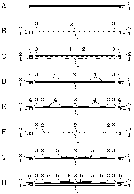
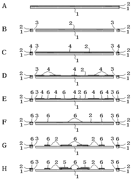
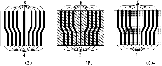
[0034] combine figure 2 and image 3 As shown, a method for forming circuit boards, the specific processed circuit boards can be PCB, FPC, TCP, COF, HDI or RF, and can be single-sided boards, double-sided boards or multi-layer boards;

[0035] Proceed as follows:

[0036] Step A:

[0037] Combining substrate 1 and copper foil 2 as a substrate; substrate 1 can choose polyimide;

[0038] Step B:

[0039] Punch out the required hole 3; the hole 3 can be a sprock...


PUM

PropertyMeasurementUnit
Thicknessaaaaaaaaaa

Abstract

The invention discloses a circuit forming method of a circuit board, and belongs to the technical field of photolithography technique. The method comprises steps: A) combining a base material and copper foil to serve as a substrate; B) punching a required hole; C) arranging a film on the surface of the copper foil; D, developing the film; E, performing graphical surface treatment on the surface ofthe copper foil to form a surface treatment layer on the surface of the copper foil; F, stripping the film; G, performing differential etching on the surface of the copper foil; and H, performing inkprinting at the corresponding position. The surface-treated non-copper substance thinner than the wet film or the dry film is adopted for differential etching, so that the updating speed of the etching solution on the surface of the to-be-etched part is higher during etching, the difference of contact between the etching solution and a copper surface is reduced, and finer circuit etching is realized. Compared with the traditional process, the surface treatment process in the method avoids long-time contact between the base material at the bottom edge of the circuit and the surface treatment liquid medicine before etching, and improves the binding force between the copper surface circuit and the base material.

Description

technical field [0001] The invention relates to the technical field of photolithography technology, in particular to a circuit forming method of a circuit board. Background technique [0002] As people's requirements for the size reduction and cost reduction of electronic equipment are getting higher and higher, in response to this requirement, the wiring of circuit boards is becoming more and more dense, that is, the line spacing and line width are gradually reduced, and The strength of this delicate line that tends to become thinner and thinner is also getting weaker. In the manufacture of circuit boards, the traditional circuit forming method is to form a window on the copper surface through a wet film or a dry film for circuit etching. This method is directly affected by the thickness of the wet film or dry film, and the contact time between the etching solution and the copper surface Become the core of production management. [0003] The traditional line forming metho...

Claims


Application Information

Patent Timeline
IPC IPC(8): H05K3/06
CPCH05K3/061H05K2203/0548
Inventor 古满香王健孙慧娟孙彬沈洪李晓华
Owner 江苏上达半导体有限公司
Learn More