
Rod milling cylinder for rod mill, cylinder cover and installation method of rod milling cylinder

A rod mill and rod mill technology, which is applied in the field of mining machinery, can solve the problems of dislocation and looseness of the cover plate, injury to the hands and feet of the operator, and difficulty in removing the cover plate.

Inactive Publication Date: 2019-11-26
TONGLING NON FERROUS METAL GROUP CORP
View PDF11 Cites 3 Cited by
  • Summary
  • Abstract
  • Description
  • Claims
  • Application Information

AI Technical Summary

Problems solved by technology

[0004] In actual use, due to design reasons, when there is dust in the bolt threads, it is difficult to tighten the bolts. Operators often need to use hands and feet to fix the sample cylinder, and then use tools to start the bolts, which is time-consuming and laborious.
Furthermore, the wear and tear of the bolts is unavoidable. When the bolts are started, the rod mill drum is often toppled due to the gaps in the bolts, which may easily cause injuries to the hands and feet of the operator and pose a safety hazard.
[0005] In addition, due to factors such as the wear of the rod mill cylinder and the deformation of the cylinder body, after the sample is rod ground, the cover plate is difficult to remove on the one hand, and at the same time, the cover plate is prone to dislocation and loosening, and sample leakage occurs during the fine crushing process of the rod mill. Stop the machine and reseal the rod mill
When the cover plate is misplaced, the operator often shakes and vibrates the rod grinding cylinder, taps the rod grinding cylinder with tools, etc. to loosen the cover plate. The labor intensity of this process increases and takes a long time. minutes, affecting the processing time of batch samples

Method used


Image

  • Rod milling cylinder for rod mill, cylinder cover and installation method of rod milling cylinder
  • Rod milling cylinder for rod mill, cylinder cover and installation method of rod milling cylinder
  • Rod milling cylinder for rod mill, cylinder cover and installation method of rod milling cylinder

Examples


Embodiment 1

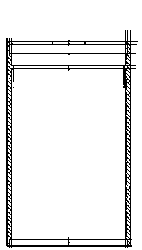
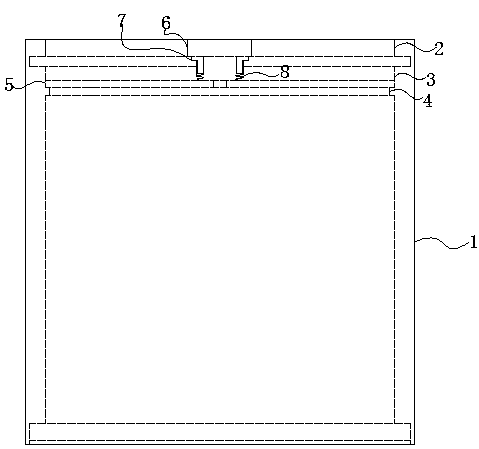
[0025] Embodiment 1: as Figure 3-5 As shown, the rod mill cylinder used for the rod mill includes a cylinder body 1 and a cylinder cover. The top of the cylinder body is provided with a circular spigot 2, and the circular spigot is provided with two diameters symmetrically with respect to the center. To the notch, the first boss 3 and the second boss 4 which are continuously distributed along the axial direction of the cylinder are provided under the circular spigot in the cylinder, and the cylinder cover includes a conformal fit on the second boss. The circular cover plate 5 on the top and the arc-shaped cover plate 6 that can conformally fit in two radial notches, the arc-shaped cover plate and the circular cover plate are concentric, and the arc-shaped cover plate passes through the rigidity in turn. The connecting piece 7 and the spring 8 are affixed to the circular cover plate.

[0026] The arc-shaped cover plate referred to here refers to the shape with a rectangle in ...

Embodiment 2

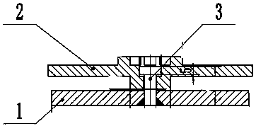
[0028] Preferred embodiment 2: as Figure 6 As shown, a cylinder 9 is affixed to the bottom surface of the arc-shaped cover plate, and a hollow cylinder 10 is affixed to the upper surface of the circular cover plate corresponding to the cylinder. The inner diameter of the cylinder is suitable, and the cylinder and the hollow cylinder are distributed at intervals under normal conditions. When the arc-shaped cover is pressed, the spring is compressed, and the cylinder will be inserted into the hollow cylinder. After testing, it was found that the arc-shaped cover plate in Example 1 would apply a radial torsion force to the spring when it rotated, and this would cause great damage to the spring. In order to avoid damage to the spring and shorten the service life of the cover, even the spring The cylinder cover cannot be taken out after being damaged, so the applicant thought that the spring should not bear the torsion force generated when the arc-shaped cover plate rotates, and h...

Embodiment 3

[0029]Preferred embodiment 3: The difference from preferred embodiment 2 is that a hollow cylinder is affixed to the bottom surface of the arc-shaped cover plate, and a cylinder is affixed to the upper surface of the circular cover plate corresponding to the hollow cylinder. The outer diameter of the cylinder matches the inner diameter of the hollow cylinder. Under normal conditions, the cylinder and the hollow cylinder are spaced apart. When the arc-shaped cover is pressed, the spring is compressed, and the cylinder will be inserted into the hollow cylinder.


PUM


Abstract

The invention discloses a rod milling cylinder for a rod mill, a cylinder cover and an installation method of the rod milling cylinder. The rod milling cylinder comprises a cylinder body (1) and a cylinder cover, wherein a circle of round spigot (2) is formed in the top of the cylinder body, two radial notches are symmetrically formed in the circular spigot in regard to the center, first bosses (3) and second bosses (4) which are continuously distributed along the axial direction of the cylinder body are arranged at the position, below the circular spigot, in the cylinder body, the cylinder cover comprises a circular cover plate (5) which can be conformal adapted to the second bossed and arc cover plates (6) which can be conformal adapted to the two radial notches, the arc cover plate sandthe circular cover plate are concentric, and the arc cover plates are fixedly connected with the circular cover plate through a rigid connecting piece (7) and a spring (8) in sequence. The rod milling cylinder has the beneficial effects that a manual self-locking device is formed by the rigid connecting piece, the spring and the arc-shaped cover plates so that the cylinder cover can be assembledand disassembled conveniently and quickly, the structure is reasonable in design, the sample is not prone to loosen and leak in sample preparation, the sample preparation quality meets the geologicalspecification requirement.

Description

technical field [0001] The invention relates to the field of mining machinery, in particular to a rod mill tube, a tube cover and an installation method of the rod mill. Background technique [0002] In the process of preparing rock and mineral samples, the rod mill is currently widely used in geological laboratories with a large amount of sample preparation because of its safety, reliability and high efficiency. The rod mill is driven by the motor through the reducer and the surrounding large gears, or the low-speed synchronous motor directly through the surrounding large gears to drive the cylinder to rotate. The barrel is equipped with a proper number of steel rods as the grinding medium. When the rod mill is working, the grinding medium is lifted to a certain height under the action of centrifugal force and friction, and is thrown or leaked in the rod mill barrel. It falls and is crushed by the moving grinding medium. The crushing force of the rod mill is mainly based ...

Claims


Application Information

Patent Timeline
IPC IPC(8): B02C17/10B02C17/18
CPCB02C17/10B02C17/18B02C17/182
Inventor 赵守恒汪宏袁自宏姜峰陈道维
Owner TONGLING NON FERROUS METAL GROUP CORP
Learn More