
Stamping device with stamping terminal capable of being subjected to shape fixing and position fixing and machining process thereof

A technology for stamping equipment and terminals, applied in the field of stamping equipment, can solve problems such as inconvenient adjustment, rupture, and impact on the quality of stamped products, and achieve the effect of avoiding stamping offset and excessive pressure.

Inactive Publication Date: 2019-11-26
SHENZHEN JIBAISHUN TECH CO LTD
View PDF7 Cites 2 Cited by
  • Summary
  • Abstract
  • Description
  • Claims
  • Application Information

AI Technical Summary

Problems solved by technology

[0004] The purpose of the present invention is to provide a stamping equipment and its processing technology for stamping terminals that can be fixed and retained, so as to solve the problem that the existing stamping terminal stamping equipment proposed in the above background technology usually fixes the stamping terminal mold. The fixed structure is relatively simple and inconvenient to adjust, and it cannot be applied to stamping terminal molds of different lengths and widths. In addition, during the hot stamping process, the temperature of the stamping terminal mold continues to rise, which may cause the mold to expand and cause local rupture, thereby affecting the quality of the stamped product. question

Method used


Image

  • Stamping device with stamping terminal capable of being subjected to shape fixing and position fixing and machining process thereof
  • Stamping device with stamping terminal capable of being subjected to shape fixing and position fixing and machining process thereof
  • Stamping device with stamping terminal capable of being subjected to shape fixing and position fixing and machining process thereof

Examples


Embodiment Construction

[0030] The following will clearly and completely describe the technical solutions in the embodiments of the present invention with reference to the accompanying drawings in the embodiments of the present invention. Obviously, the described embodiments are only some, not all, embodiments of the present invention. Based on the embodiments of the present invention, all other embodiments obtained by persons of ordinary skill in the art without making creative efforts belong to the protection scope of the present invention.

[0031] In the description of the present invention, unless otherwise stated, the meaning of "plurality" is two or more; the terms "upper", "lower", "left", "right", "inner", "outer" , "front end", "rear end", "head", "tail", etc. indicate the orientation or positional relationship based on the orientation or positional relationship shown in the drawings, and are only for the convenience of describing the present invention and simplifying the description, rather...


PUM


Abstract

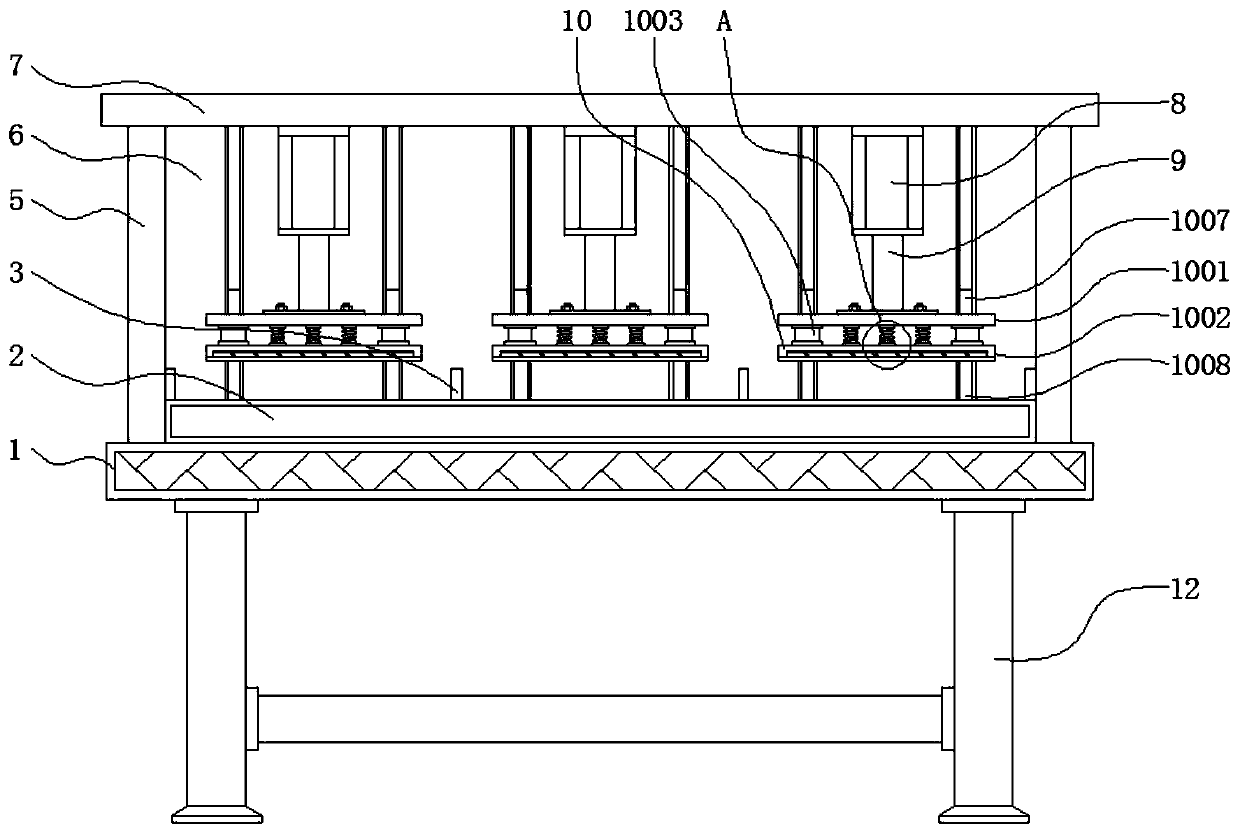
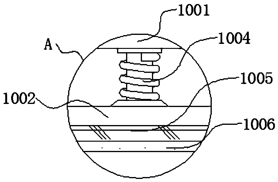
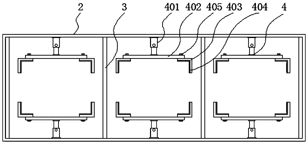
The invention discloses a stamping device with a stamping terminal capable of being subjected to shape fixing and position fixing and a machining process thereof, and relates to the technical field ofstamping terminals of stamping devices. The device comprises a mounting base, a fixing mechanism and a stamping mechanism, a stamping table is arranged in the middle of the upper portion of the mounting base, a partition plate is fixed above the stamping table, the fixing mechanism is mounted on the inner side above the stamping table, supporting rods are welded to the two sides of the upper portion of the mounting base, a back plate is fixed to the rear side of the upper portion of the mounting base, a top plate is fixed above the supporting rods, and an air cylinder is arranged below the middle of the top plate. The device has the beneficial effects that through a telescopic rod, the position of a positioning plate can be telescopically adjusted conveniently, the device can convenientlyadapt to stamping terminal molds of different widths, through cooperation of sliding blocks and sliding grooves, the position of a positioning block can be conveniently adjusted in a sliding manner,the device can conveniently adapt to stamping terminal molds of different lengths, the positioning block is of an L structure, and the four corners of the stamping terminal mold can be subjected to uniform limiting and fixing.

Description

technical field [0001] The invention relates to the technical field of stamping equipment for stamping terminals, in particular to a stamping equipment capable of solid-retaining stamping terminals and a processing technology thereof. Background technique [0002] The terminal is the part where the battery is connected to the external conductor. Their function is mainly to transmit electrical signals or to conduct electricity. In electrical engineering, terminals refer to terminal terminals, also called terminal blocks. Stamping equipment is the so-called press, which is a large special equipment for pressing containers. In the process of stamping terminals, stamping equipment is needed to stamp them to form them. [0003] The existing stamping equipment for stamping terminals generally uses a simple fixing structure and is inconvenient to adjust when fixing the stamping terminal mold, and cannot be applied to stamping terminal molds of different lengths and widths. The ...

Claims


Application Information

Patent Timeline
Patent Type & Authority Applications(China)
IPC IPC(8): B21D22/02B21D37/16
CPCB21D22/02B21D37/16
Inventor 曹青山刘瑞
Owner SHENZHEN JIBAISHUN TECH CO LTD
Learn More