
RIC finger sleeve underwater medium hydraulic shearing device

A technology of shearing device and finger casing, which is applied in the field of reactor pressure vessel maintenance, can solve the problems of not being able to return to the initial position completely, foreign matter falling into the core, and affecting the safety of the core, so as to solve the problem of safety and the reset of the movable blade problem effect

Inactive Publication Date: 2019-11-26
CNNC FUJIAN FUQING NUCLEAR POWER
View PDF4 Cites 0 Cited by
  • Summary
  • Abstract
  • Description
  • Claims
  • Application Information

AI Technical Summary

Problems solved by technology

[0003] At present, the existing RIC finger-casing hydraulic shearing device is placed on the upper end of a special container to cut the finger-casing. ) may cause foreign matter to fall into the core, affecting the safety of the core
Moreover, the current hydraulic shearing device uses a single-acting hydraulic cylinder for shearing action and uses a spring to reset. Since the shearing is performed at a place about 7.5m below the water surface of the core pool, the height difference from the hydraulic pump is about 8m, and the spring completely relies on the spring to overcome the 8m. The difference in water pressure causes the moving blade to return slowly or even not fully return to the original position
If the spring force is increased to overcome the water pressure difference to complete the reset of the movable blade, the output pressure of the hydraulic pump needs to be increased (in order to overcome the spring force), which will lead to disadvantages such as bulky structure and inconvenient use.

Method used


Image

  • RIC finger sleeve underwater medium hydraulic shearing device

Examples


Embodiment Construction

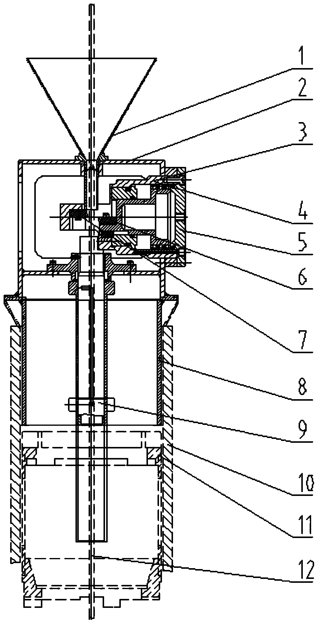
[0013] A kind of RIC refers to casing underwater water medium hydraulic shearing device, comprising a conical guide cylinder 1, a shear box 2, a square positioning sleeve 8 and a lower guide sleeve 9, wherein the conical guide cylinder 1 has a funnel-shaped structure, and its Installed on the upper end of the shear box 2, it guides the finger sleeve 12 put into the tapered guide cylinder 1, so that the finger sleeve 12 can enter the shear box 2 in the vertical direction; it is fixed inside the shear box 2 A shearing cylinder is installed to shear the finger sleeve 12 inserted into the shear box 2 through the tapered guide cylinder 1, wherein the shearing cylinder includes a cylinder body 3, a piston 4 and a shearing blade, and the cylinder body 3 is integrally fixed inside the shell of the shear box 2, and an oil channel is provided on the cylinder body 3, and the oil channel opening of the cover is at the front end of the cylinder body 3; the piston 4 is installed inside the c...


PUM


Abstract

The invention provides an RIC finger sleeve underwater medium hydraulic shearing device. The RIC finger sleeve underwater medium hydraulic shearing device comprises a conical guide barrel, a shearingbox, a square positioning sleeve and a lower guide sleeve. The conical guide barrel is mounted at the upper end of the shearing box. A shearing cylinder is fixedly mounted in the shearing box, and a finger sleeve stretching into the shearing box through the conical guide sleeve is shorn, wherein the shearing cylinder comprises a cylinder body, a piston and a shearing blade, the cylinder body is fixed into a shearing box shell, an oil way passageway is formed in the cylinder body, and an opening of the oil way passageway is formed in the front end in the cylinder body. The piston is mounted inthe cylinder body, a cylinder cover is mounted on the rear portion of the cylinder body, and two through holes are formed in the cylinder cover, wherein the middle through hole is connected with the rear end of the piston, and the through hole in the outer side of the cylinder cover is connected with the oil way passageway of the cylinder body and connected with the front end of the piston. The shearing blade comprises a movable blade body and a fixed blade body, wherein the fixed blade body is mounted on the inner side of the front end of the cylinder body of the shearing cylinder, and the movable blade body is mounted at the front end of the piston of the shearing cylinder.

Description

technical field [0001] The invention belongs to the technical field of reactor pressure vessel maintenance, and in particular relates to an RIC finger casing underwater water medium hydraulic shearing device. Background technique [0002] During the long-term operation of a nuclear power plant, changes in the flow of coolant at the bottom of the pressure vessel and vibration induced by the fluid will lead to wear of the RIC bushing. When the wall thickness of the RIC finger cannula is reduced to 65%, foreign matter is blocked, broken, or accidentally damaged, the finger cannula needs to be replaced. Scissors are required to cut off the discarded finger casing of the activation section in the reactor pressure vessel, so that it can be stored in a special container to ensure the safe operation of the nuclear power plant. [0003] At present, the existing RIC finger-casing hydraulic shearing device is placed on the upper end of a special container to cut the finger-casing. ) ...

Claims


Application Information

Patent Timeline
Patent Type & Authority Applications(China)
IPC IPC(8): B23D15/04B23D15/14B23D21/00
CPCB23D15/04B23D15/14B23D21/00
Inventor 向先保郭轶波祝飞黄帅闵济东江浩仁黄成龙邓鹏辉贾仲林
Owner CNNC FUJIAN FUQING NUCLEAR POWER
Learn More