
In-situ inspection machine for CNC machining workpiece based on binocular vision

A technology for processing workpieces and binocular vision, applied in metal processing machinery parts, metal processing equipment, manufacturing tools, etc., can solve problems such as secondary clamping errors, and achieve the effect of ensuring high precision and large detection range

Active Publication Date: 2021-04-30
安徽爱力特装备科技有限公司
View PDF7 Cites 0 Cited by
  • Summary
  • Abstract
  • Description
  • Claims
  • Application Information

AI Technical Summary

Problems solved by technology

[0002] In the process of CNC machine tool processing, it is an important process to detect the dimensional accuracy of the workpiece after completing a process. Traditional detection tools such as micrometers, three-coordinate measuring instruments, etc. can complete the overall shape measurement, and the operation is simple. However, traditional measurement methods It is necessary to remove the workpiece from the processing station and then inspect it. After the inspection, redefine the new reference plane and re-clamp and fix it, which will inevitably cause secondary clamping errors.

Method used


Image

  • In-situ inspection machine for CNC machining workpiece based on binocular vision
  • In-situ inspection machine for CNC machining workpiece based on binocular vision
  • In-situ inspection machine for CNC machining workpiece based on binocular vision

Examples


Embodiment Construction

[0021] The present invention will be further described below in conjunction with the accompanying drawings and embodiments.

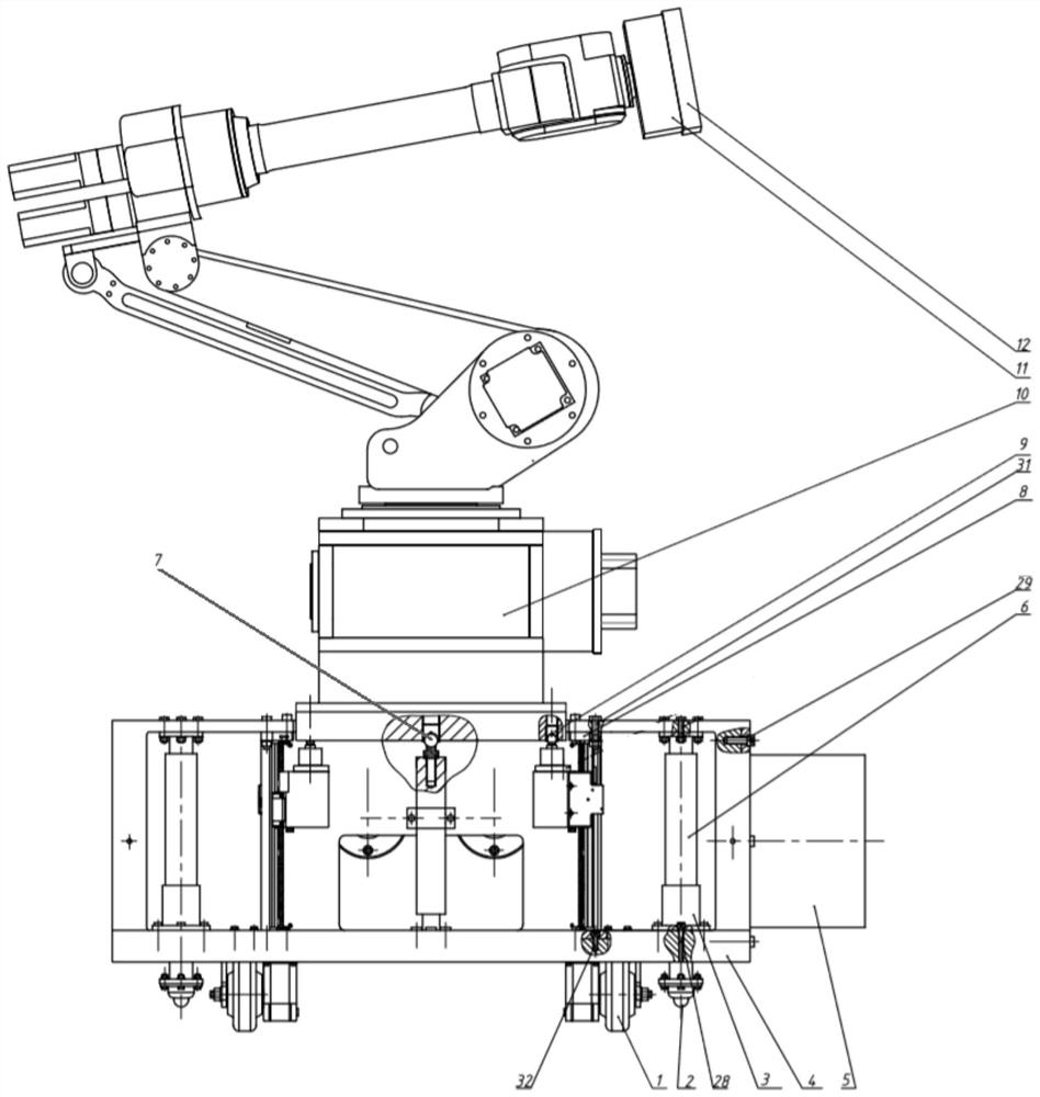
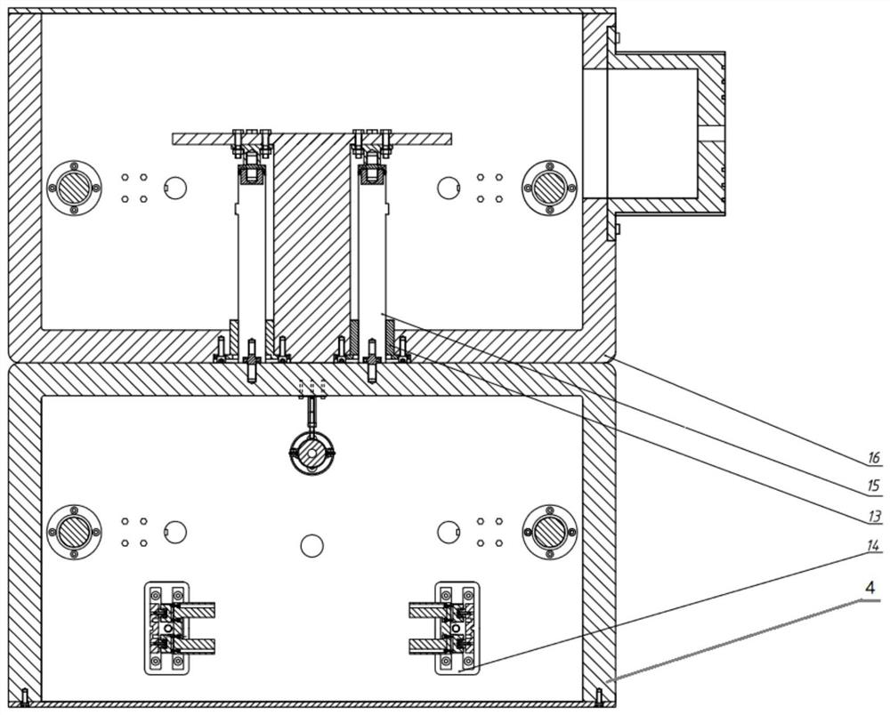
[0022] see Figure 1-5 , the present invention's binocular vision-based numerical control processing workpiece in-position detection machine is composed of a binocular detection component, a self-adjusting level device component, a positioning guide component and a base component.

[0023] The binocular detection part includes a binocular camera shield 12, a binocular camera 11, and a mechanical arm part 10. The binocular camera 11 is connected to the execution end of the mechanical arm part 10 by screws, and the mechanical arm part 10 is connected to the self-adjusting horizontal base by screws. 24 connection, the base parts include the front body positioning base 4, the back body positioning base 16, the front and rear telescopic rod assembly 15, the guide positioning plate 13, the front and rear telescopic rod assembly 15 includes a positioning flang...


PUM


Abstract

The invention relates to a binocular vision-based numerical control processing workpiece in-position detection machine, which has a binocular detection part, and the binocular detection part is installed on a self-adjusting level device part, and the binocular detection part is automatically adjusted through the self-adjusting level device part. The detection reference of the detection part ensures the detection accuracy of the binocular detection; the self-adjusting level device part is placed in the base of the base part, and the side of the base part of the base part is equipped with an electromagnetic adsorption end of the positioning guide part, and the base The wheel set is installed below to realize the movement of the entire base. The shell of the electromagnetic adsorption end has a built-in laser sensor, which is used to control the in-position detector to move to the required measurement position, and is adsorbed on the machine tool through the electromagnetic adsorption end. , to realize the positioning of the in-position detection machine relative to the machine tool. The invention realizes the in-position detection mechanism of the workpiece through the combination of the binocular detection part, the self-adjusting level device part and the positioning guide part, and can also adapt to the in-position detection of the workpiece of different types of machine tools.

Description

technical field [0001] The invention relates to a processing workpiece in-position detection machine, which can be adapted to the workpiece in-position detection of different types of numerical control machine tools in complex working environments. Background technique [0002] In the process of CNC machine tool processing, it is an important process to detect the dimensional accuracy of the workpiece after completing a process. Traditional detection tools such as micrometers, three-coordinate measuring instruments, etc. can complete the overall shape measurement, and the operation is simple. However, traditional measurement methods It is necessary to remove the workpiece from the processing station and then inspect it. After the inspection, redefine a new reference plane and re-clamp and fix it, which will inevitably cause secondary clamping errors. Therefore, it is necessary to design an in-position detection device to realize the in-position detection of the workpiece in ...

Claims


Application Information

Patent Timeline
Patent Type & Authority Patents(China)
IPC IPC(8): B23Q17/20
CPCB23Q17/20
Inventor 林献坤陈飒繆建淘
Owner 安徽爱力特装备科技有限公司
Learn More