In-situ detection device and method for flatness of ultra-precision grinding large-diameter optical components

A technology of optical components and detection methods, applied in the direction of using optical devices, measuring devices, instruments, etc., can solve problems such as unsatisfactory measurement accuracy, achieve the effects of avoiding repeated processing, suppressing environmental errors, and improving processing efficiency

Inactive Publication Date: 2015-10-07
SHANGHAI UNIV
View PDF12 Cites 0 Cited by
  • Summary
  • Abstract
  • Description
  • Claims
  • Application Information

AI Technical Summary

Problems solved by technology

In 1986, the DPM method (Discrete Phase Method) proposed by Stuhlinger et al. used the overlapping area between the sub-apertures for the first time to estimate the relative translation and tilt of the sub-apertures through least-squares fitting. However, due to the influence of mechanical movement errors, the measurement accuracy not ideal

Method used


Image

  • In-situ detection device and method for flatness of ultra-precision grinding large-diameter optical components
  • In-situ detection device and method for flatness of ultra-precision grinding large-diameter optical components
  • In-situ detection device and method for flatness of ultra-precision grinding large-diameter optical components

Examples


Embodiment Construction

[0029] The present invention will be described in further detail below in conjunction with the accompanying drawings and embodiments.

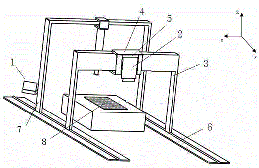
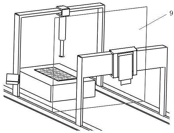
[0030] see figure 1 , an ultra-precision grinding large-caliber optical element flatness in-position detection device, including a computer 1, a dynamic interferometer 2, a main measurement stand 3, an x-direction guide rail 4, a z-direction guide rail 5, a stand guide rail 6, and an isolation device 9. The dynamic interferometer 2 is installed on the guide rail 5 in the z direction, and is used to measure each sub-aperture data of the measured surface 8, which is transmitted to the computer 1 for processing, and the main mirror of the dynamic interferometer 2 is provided with a closed cover; The main measurement platform 3 is an independent movable gantry structure, which moves along the platform guide rail 6, and the x-direction guide rail 4 and the z-direction guide rail 5 for moving the dynamic interferometer 2 horizontally are installed o...


PUM


Abstract

The invention discloses an in-place detection device and method for the planeness of an ultra-precise grinding large-aperture optical element. The detection device comprises a computer, a dynamic interferometer, a main measuring stand, an x-direction guide rail, a z-direction guide rail, a stand guide rail and an isolating device. The detection device combines a detection device for a planeness error of the large-aperture optical element with a grinding machine to achieve in-place detection of the optical element, so that the processing efficiency is improved greatly, and the introduction error during carrying of an element to be tested is reduced to the utmost extent. The detection device and the ultra-precise grinding machine adopt a separated structure, so that not only can the precision of the detection device be prevented from being influenced by the working vibration of the grinding machine, but also the detection device can be used independently as universal equipment for in-place detection of the planeness of the large-aperture optical element. The detection method adopts a stitching interferometer technology and uses the high-precision three-dimensional movement of the dynamic interferometer in the device to achieve subaperture measurement; and further, the size range of the detectable element is enlarged, the environmental error of a workshop is restrained effectively, and the detection precision is improved.

Description

technical field [0001] The invention relates to an in-position detection device and method for the flatness of an ultra-precision grinding large-diameter optical element, and belongs to the technical field of geometric quantity measurement of large-diameter optical elements. Background technique [0002] With the development of modern aviation, aerospace, military and other technologies, the application of large-aperture optical components is becoming more and more extensive, and the precision requirements are getting higher and higher. In the process of processing large-aperture optical components, it needs to be inspected many times to ensure the processing accuracy. At present, the detection method of large-aperture optical components is basically offline detection, and it needs to be transported to a remote place with a large-aperture detection device for detection. This method is not only time-consuming but also causes multiple installation errors, and is only suitable ...

Claims


Application Information

Patent Timeline
Patent Type & Authority Patents(China)
IPC IPC(8): G01B11/30G01B11/24
Inventor 武欣于瀛洁王伟荣忻晓蔚张小强
Owner SHANGHAI UNIV
Why Eureka
Try Eureka