Movable robot

A mobile and robotic technology, applied in the field of robotics, can solve the problems of increasing the weight of the robot, the inability to carry path planning, and the high requirements for the drive motor, and achieve the effects of high cost, reduced weight of the entire machine, and high power-to-mass ratio

Active Publication Date: 2019-11-26
HANGZHOU TIANMING TECH CO LTD
View PDF6 Cites 1 Cited by
  • Summary
  • Abstract
  • Description
  • Claims
  • Application Information

AI Technical Summary

Problems solved by technology

In an open workplace, it is impossible to plan the handling path according to the location of the goods, and automatically complete the loading and unloading of the goods
[0004] The robotic arm is the most important and core component of the robot. Most of the robotic arms currently on the market are joint-type, and the movement of the robotic ar

Method used


Image

  • Movable robot
  • Movable robot
  • Movable robot

Examples


Embodiment 1

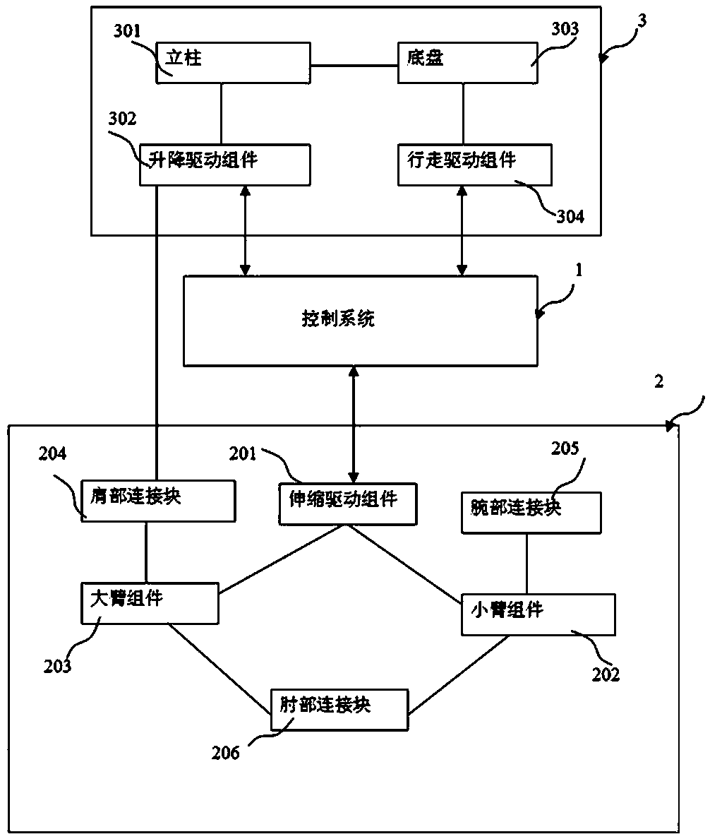
[0051] refer to figure 1 , the figure is the structural block diagram of the robot of the present invention, including a control system 1, which is used to receive information and control the mobile lifting column 3 and the mechanical telescopic arm 2 according to the information and control algorithm; , to achieve movement and / or zero-radius rotation according to the instructions of the control system; the mechanical telescopic arm 2 is slidably connected to the mobile lifting column 3 through the shoulder connecting block 204, and completes the vertical lifting motion according to the instructions of the control system, and is in the Under the control of the control system, the telescopic movement in the horizontal direction is carried out through the telescopic movement of the mechanical arm.

[0052] Specifically, the mechanical telescopic arm includes a large arm assembly 203 and a small arm assembly 202. The large arm assembly 203 and the small arm assembly 202 are rotat...

Embodiment 2

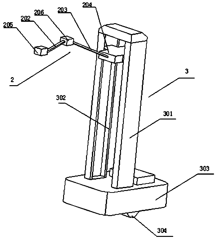
[0064] refer to image 3 , the figure is a schematic structural diagram of an embodiment of the robot of the present invention,

[0065] The robot includes a mechanical telescopic arm 2 and a mobile lifting column 3 , and the mobile lifting column 3 is connected with the mechanical telescopic arm 2 . The mechanical telescopic arm 2 includes a large arm assembly 203, a small arm assembly 202, a shoulder connecting block 204, an elbow connecting block 206 and a wrist connecting block 205; one end of the large arm assembly 203 is rotatably connected to the shoulder connecting block 204. The other end of the arm assembly 203 is rotatably connected to the elbow connecting block 206 ; The moving lift column 3 includes a column 301 , a lift drive assembly 302 and a chassis 303 . The column 301 is fixedly installed on the chassis 303 , and the lift drive assembly 302 is slidably installed inside the column 301 . The control system is installed inside the chassis 303 . In this embod...

Embodiment 3

[0067] refer to Figure 4 , is a schematic structural diagram of a mechanical telescopic arm of the robot of the present invention,

[0068] The boom assembly 203, the shoulder connecting block 204, and the elbow connecting block 206 are connected by rotation to form a parallelogram, in which the two sides of the boom assembly 203 can move relative to each other; the forearm assembly 202, the elbow connecting block 206, The wrist connecting block 205 forms a parallelogram through rotational connection, and the two sides of the small arm assembly 202 in the parallelogram can move relative to each other. The telescopic drive assembly 201 is composed of a first drive rod 2012, a second drive rod 2013 and a drive block 2011. The first drive rod 2012, the second drive rod 2013, the boom assembly 203, the forearm assembly 202 and the drive block 2011 are connected by rotation A parallelogram is formed, the driving block 2011 is slidably connected to the shoulder connecting block, a...


PUM


Abstract

The invention discloses a movable robot. The movable robot is composed of a movable lifting column, a mechanism type stretchable arm and a control system, the movable robot can walk freely on the ground, and a carrying path is planned according to an initial position and an end point position of a target object. Compared with a fixed stacking robot, the movable robot can realize multi-position stacking and carrying of the target object, and the application scene is more flexible. A rotary table structure of the fixed type stacking robot is replaced with the in-situ rotation of the movable lifting column, the mechanism type stretchable arm is adopted to replace a joint type swinging arm and a rail type movable arm, so that the structure of the whole machine is simpler, the power mass ratiois higher, the power consumption of the whole machine and the weight of the whole machine are greatly reduced.

Description

technical field [0001] The invention relates to the technical field of robots, in particular to a mobile robot. Background technique [0002] The advancement of modern technology and industrial technology has made robots show strong vitality in various industries. The breadth of robots used in society and the depth of their own technical research have become a measure of a country's industrial intelligence level. Robots are the product of the organic combination of machinery and computer programs, providing higher production efficiency for modern production. Machines are widely used in the industry, which can greatly save labor and improve work efficiency. [0003] At present, robots that can handle heavy items (such as more than 100kg) have a fixed working position, and are generally fixed beside the production line for assembly or handling of objects on the assembly line. In an open workplace, it is impossible to plan the transportation path according to the location of t...

Claims


Application Information

Patent Timeline
IPC IPC(8): B25J5/00B25J18/02
CPCB25J5/007B25J18/025
Inventor 杨惠忠卿兆波
Owner HANGZHOU TIANMING TECH CO LTD
Why Eureka
Try Eureka