
A mold and prefabrication method suitable for producing assembled underpass tunnel frames by long-line matching method

A long-term matching and assembly technology, applied in the direction of molds, etc., can solve the problems of high cost, high construction risk, and low precision of component prefabrication

Active Publication Date: 2020-10-23
成都城投城建科技有限公司
View PDF7 Cites 0 Cited by
  • Summary
  • Abstract
  • Description
  • Claims
  • Application Information

AI Technical Summary

Problems solved by technology

[0005] The purpose of the present invention is to provide a method that can reduce the difficulty of prefabricated construction, save construction costs, reduce construction risks and improve the quality of the tunnel frame due to the shortcomings of high cost, high construction risk, and low prefabricated precision in the current tunnel frame component prefabrication construction. Prefabrication device for prefabricated precision of prefabricated components

Method used


Image

  • A mold and prefabrication method suitable for producing assembled underpass tunnel frames by long-line matching method
  • A mold and prefabrication method suitable for producing assembled underpass tunnel frames by long-line matching method
  • A mold and prefabrication method suitable for producing assembled underpass tunnel frames by long-line matching method

Examples


Embodiment 1

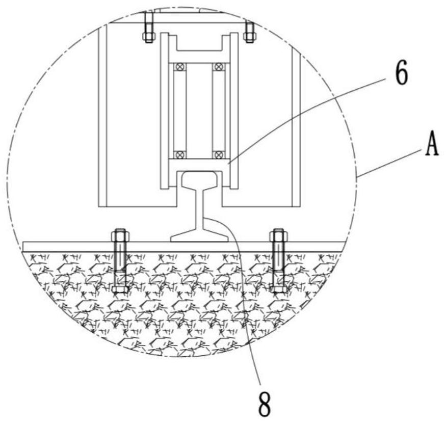
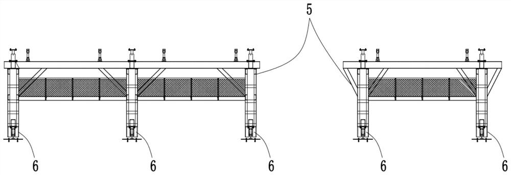
[0051] Example 1, such as Figure 1-8 Shown:

[0052] A mold suitable for producing an assembled underpass tunnel frame by the long-line matching method, including a bottom mold assembly 2 adapted to the bottom of a frame segment 1, and an inner mold assembly 11 adapted to the inner wall of the frame segment 1 , a side mold assembly 3 adapted to the outer walls on both sides of the frame segment 1 and an end mold assembly adapted to both ends of the frame segment 1, and an inner mold for supporting the inner mold assembly 11 The bracket 5 is provided with a driving device for driving the inner mold assembly 11 to switch between the pouring position and the disengagement position on the inner mold bracket 5, and the first walking assembly 6 is also arranged on the inner mold bracket 5, so The first walking assembly 6 is used to provide the movement of the inner mold support 5 along the length direction of the frame.

[0053] In this scheme, the frame segment 1 is formed by di...

Embodiment 2

[0068] Example 2, such as Figure 1-8 as shown,

[0069] A prefabrication method for prefabrication of a tunnel frame segment 1 using the mold described above,

[0070] Three work areas are sequentially numbered along the length direction of the track 8 to form: the first work area, the second work area and the third work area. The prefabrication method of this embodiment includes the following steps set in sequence:

[0071] Step 1. Prefabrication of the first frame segment 1 in the first working area: assemble the bottom mold assembly 2, the side mold assembly 3, the end mold assembly and the inner mold assembly 11 in the first working area to form a The pouring cavity with the same shape as the first frame segment 1, in which the pre-embedded components are installed and the concrete is poured;

[0072] Step 2. Prefabrication of the first frame segment 1 in the second working area: After the frame segment 1 in step 1 is hardened, the end formwork assembly and the side for...


PUM


Abstract

The invention relates to the technical field of building engineering, in particular to a mold suitable for producing a fabricated undercrossing channel frame through a long-line matching method and aconstruction method. The mold comprises bottom mold assemblies matched with the bottom of a frame segment, inner mold assemblies matched with the inner wall of the frame segment, side mold assembliesmatched with the outer walls of the two sides of the mold segment and end mold assemblies matched with the two ends of the mold frame. The mold further comprises an inner mold support used for supporting the inner mold assemblies. A drive device used for driving the inner mold assemblies to be switched between a pouring position and a separation position is arranged on the inner mold support. First walking assemblies are further arranged on the inner mold support and are used for proving movement in the length direction of the frame for the inner mold support.

Description

technical field [0001] The invention relates to the technical field of construction engineering, in particular to a mold suitable for producing an assembled underpass tunnel frame by a long-line matching method and a construction method. Background technique [0002] In the field of construction engineering technology, in the construction of urban underpass tunnels, when prefabricating the frame of prefabricated urban underpass tunnels, the traditional process usually uses stereotyped combined steel molds for independent production, that is, the pre-embedded components are first designed and installed, and then The installation and adjustment of the pouring formwork, and then the concrete pouring construction, after the pouring is completed, maintenance, and finally transfer and storage, that is, the prefabrication of the tunnel frame is completed. Although this method is widely used in the current tunnel frame prefabrication, it is still There are still deficiencies, as fol...

Claims


Application Information

Patent Timeline
Patent Type & Authority Patents(China)
IPC IPC(8): B28B7/22
CPCB28B7/22
Inventor 李鑫肖东王杰谭琪刘佳欣郑洲徐兵
Owner 成都城投城建科技有限公司
Learn More