
Method for waste rock cementing filling after up-caving open stoping

A technology of cemented filling and stone glue, which is applied in the direction of filling, earthwork drilling, safety devices, etc., can solve the problem that the strength of the filling body cannot meet the technical requirements, the filling slurry cannot completely fill the voids of waste rock, and increase Problems such as large ore loss and dilution, to solve the ore loss, reduce the time required for filling, and enhance the mixing effect

Active Publication Date: 2019-11-26
CENT SOUTH UNIV
View PDF6 Cites 2 Cited by
  • Summary
  • Abstract
  • Description
  • Claims
  • Application Information

AI Technical Summary

Problems solved by technology

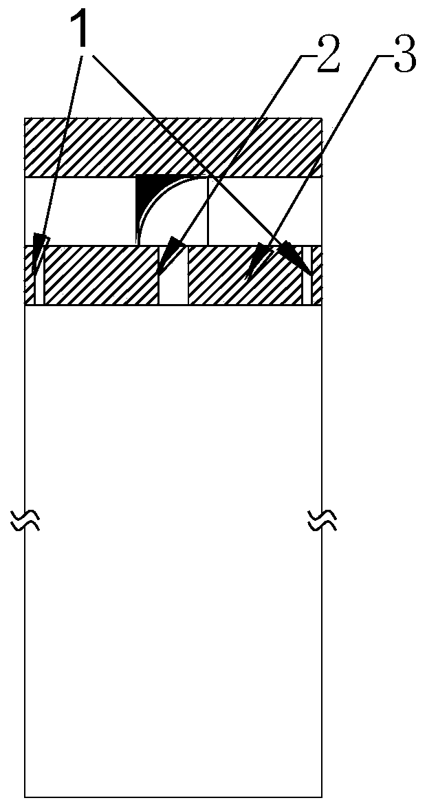
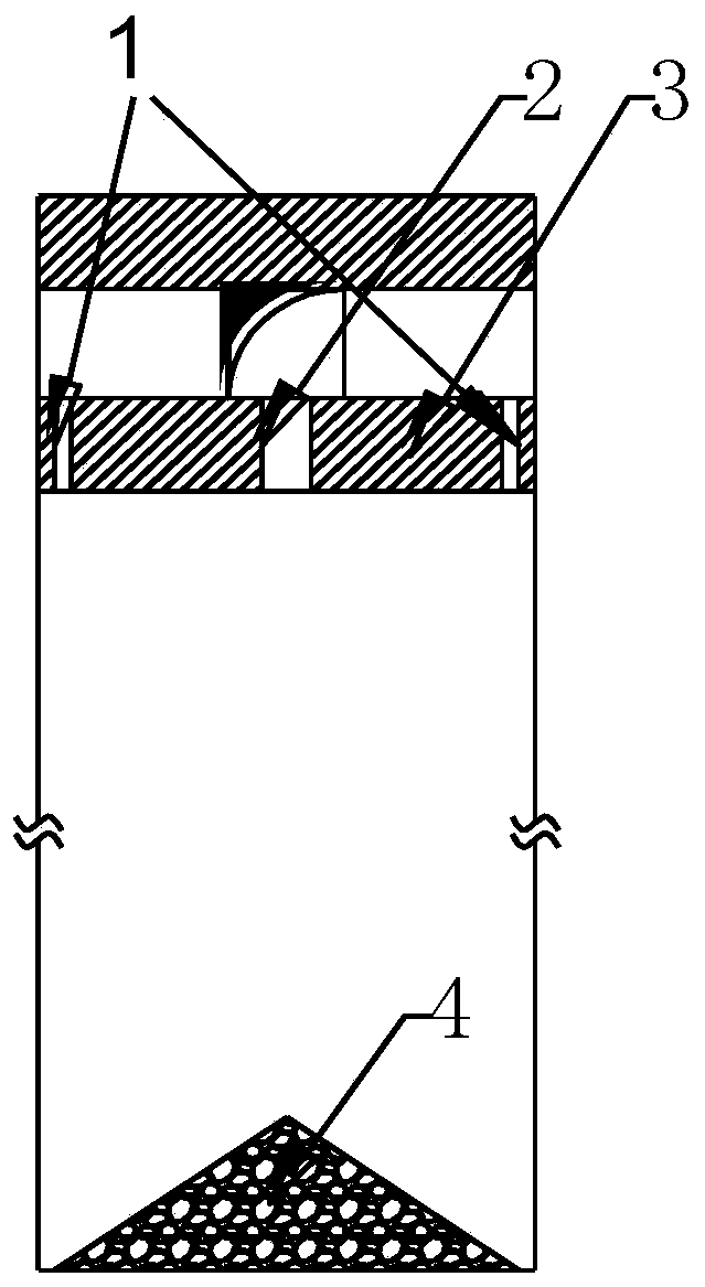
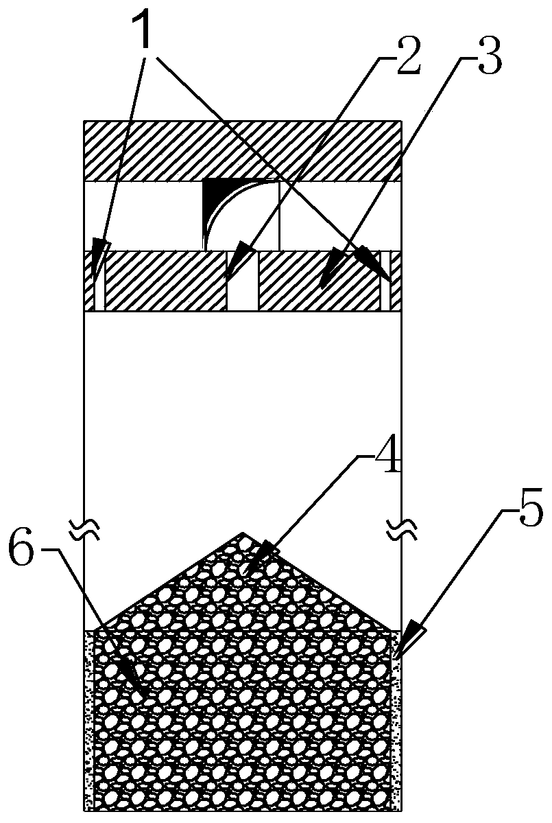
[0003] During the waste rock cemented filling process, since the waste rock is backfilled by gravity from the upper measure well, the waste rock will continuously wash away the side wall of the second-step ore pillar, destroying its regularity, causing a large amount of filling body to be mixed into the ore during the second-step mining, increasing the Ore loss and dilution; at the same time, because the current construction process is to pour the tailings filling slurry after the waste rock backfilling work is completed, and the current filling slurry is mostly paste or paste-like, and the fluidity of the slurry is poor, making the filling material The slurry cannot completely fill the voids of the waste rock, and the mixing effect is poor, resulting in the strength and stability of the filling body not meeting the technical requirements

Method used


Image

  • Method for waste rock cementing filling after up-caving open stoping
  • Method for waste rock cementing filling after up-caving open stoping
  • Method for waste rock cementing filling after up-caving open stoping

Examples


Embodiment Construction

[0037] The technical solutions of the present invention will be clearly and completely described below in conjunction with the accompanying drawings. Apparently, the described embodiment is one embodiment of the present invention, but not all embodiments. Based on the embodiments of the present invention, all other embodiments obtained by persons of ordinary skill in the art without making creative efforts belong to the protection scope of the present invention.

[0038] In the description of the present invention, it should be noted that the orientations or positional relationships indicated by the terms "center", "upper", "lower", "left", "right", "inner", "outer" etc. are based on the attached The orientation or positional relationship shown in the figure is only for the convenience of describing the present invention and simplifying the description, and does not indicate or imply that the referred device or element must have a specific orientation, be constructed and opera...


PUM


Abstract

The invention belongs to the technical field of underground mine exploitation, and particularly relates to a method for waste rock cementing filling after up-caving open stoping. The method is used for solving the problems of the poor mixing effect of waste rock and cementing filling slurry during conventional waste rock cementing filling, non-standard filling body strength and stability, breakingof two-step pillar regularity during waste rock filling and the like. The method comprises the following steps that firstly, waste rock backfilling wells and filling holes are formed in a roof of a mining room, then waste rock backfilling and cementing filling slurry filling are carried out, the backfilling amount and cementing filling slurry blanking amount and proportion are adjusted during filling, cementing filling body protection wall layers are formed before the waste rock reaches the boundary of the mine room, two-step pillars are protected, the waste rock is prevented from eroding theside walls of the two-step pillars, waste rock backfilling and cementing filling slurry filling are carried out at the same time, the filling efficiency is improved, the mixing effect of the waste rock and the filling slurry is improved, and the strength and the stability of the filling body meet the technical requirements.

Description

technical field [0001] The invention relates to the technical field of underground mining, in particular to an ascending empty field followed by waste rock cemented filling method. Background technique [0002] At present, the indicators for evaluating the filling effect in the mining industry mainly include filling body strength, filling body stability and filling speed. Among the applied filling mining methods, the waste rock cemented filling mining method is widely used. This method can effectively utilize the waste rocks generated in the mining process, reduce the transportation cost of waste rocks, avoid environmental and ecological pollution and economic expenditures caused by the accumulation of waste rocks on the surface, and at the same time effectively deal with the gobs and avoid the occurrence of surface waste rocks. Subsidence and other hazards. [0003] During the waste rock cemented filling process, since the waste rock is backfilled by gravity from the uppe...

Claims


Application Information

Patent Timeline
Patent Type & Authority Applications(China)
IPC IPC(8): E21F15/00
CPCE21F15/00E21F15/005
Inventor 胡建华丁啸天罗周全任启帆匡也周坦
Owner CENT SOUTH UNIV
Learn More