Bridge pier and abutment scour preventing apparatus with vortex generators

a technology of vortex generators and bridge piers, which is applied in the field of civil engineering, hydraulic engineering, soil and water conservation, can solve the problems of scour, highway bridge failure, and significant cost and risk in the maintenance of many bridges throughout the world, and achieve the effects of preventing the separation of the downstream part, eliminating the flow leading, and reducing the 3d separation

Active Publication Date: 2012-05-31
APPLIED UNIV RES
View PDF2 Cites 16 Cited by
  • Summary
  • Abstract
  • Description
  • Claims
  • Application Information

AI Technical Summary

Benefits of technology

[0011]In general, a single, fully three-dimensionally shaped optimized fairing with the help of specially designed vortex generators will prevent scour for a range of angles between the on-coming river flow and the pier centerline from −20° to +20°, with 0 angle defined when the flow is aligned with the pier centerline axis or side of an abutment.
[0012]One can generalize the use of the vortex generators for various cases and applications. First, the vortex generators, such as the low drag asymmetric vortex generator (VorGAUR™), should be located on the sides of the fairing well upstream of any adverse or positive pressure gradients and only in flow regions where there are zero pressure gradients or favorable or negative pressure gradients that will persist downstream of the vortex generator for at least one vortex generator length. This results in a well-formed vortex without flow reversal that can energize the downstream flow and prevent separation of the downstream part of the fairing. Secondly, the vortex generator should be at a modest angle of attack angle of the order of 10 to 20 degrees. Multiple vortex generators may be used on the sides of the fairing, as shown in FIGS. 5 and 6. The height and maximum width of the vortex generators need not be greater than the thickness of the approaching turbulent boundary layer upstream of the location of the vortex generators. The spacing between the vortex generators up the side of the fairing should be at least twice the maximum width of the vortex generator or twice the length of the vortex generator times the sine of the angle of attack, whichever is larger.
[0013]A fluid mechanics engineer of ordinary skill would be able to implement the invention herein using and understanding the nomenclature (pressure gradients, stream-wise gradient of surface vorticity flux, vorticity diffusion rate, boundary layer thickness, angle of attack) and be able to compute the unseparated flow over an upstream part of a body (i.e., a fairing, pier, or abutment) and determine the locations where the flow has a zero or negative pressure gradient, the boundary layer thickness along the flow over the object, and the locations and regions downstream of the vortex generators where the pressure gradient would be negative or positive. These basic computations would enable, in accord with the principles of the invention, the sizing and shaping of the respective fairing and vortex generators and the positioning and implementation of the one or more vortex generators to energize the flow at discrete locations and eliminate the flow leading to riverbed scour.
[0014]The innovative scour prevention device in this present invention belongs to the structural countermeasure category. Unlike the conventional structural countermeasures, this scour countermeasure device is invented based on a deep understanding of the scour mechanisms of the flow and consideration of structural and hydraulic aspects (Simpson 2001). A hydraulically optimum pier fairing prevents the formation of highly coherent vortices around the bridge pier or abutment and reduces 3D separation downstream of the bridge pier or abutment with the help of the vortical flow separation control technique developed here.
[0015]In addition, these results show that the smooth flow over the pier or abutment produces lower drag force or flow resistance and lower flow blockage because low velocity swirling high blockage vortices are absent. As a result, water moves around a pier or abutment faster above the river bed, producing a lower water level at the bridge and lower over-topping frequencies on bridges during flood conditions FOR ANY WATER LEVEL, INFLOW TURBULENCE LEVEL, or INFLOW SWIRLING FLOW LEVEL. While tested at model scale, there was NO place for debris to get caught or NO DEBRIS BUILD UP in front or around a pier or abutment with the scAUR™ and VorGAUR™ products. In cases where river or estuary boat or barge traffic occurs, the scAUR™ fairing can be constructed to withstand impact loads and protect piers and abutments.

Problems solved by technology

Removal of river bed substrate around bridge pier and abutment footings, also known as scour, presents a significant cost and risk in the maintenance of many bridges throughout the world.
Bridge scour at the foundations of bridge piers and abutments is one of the most common causes of highway bridge failures.
Unfortunately, all such countermeasures currently in existence and practice are temporary responses that cannot endure throughout the lifetime of the bridge and do not prevent the formation of scouring vortices, which is the root cause of the local scour.
Consequently, sediment such as sand and rocks from around the foundations of bridge abutments and piers is loosened and carried away by the flow during floods, which may compromise the integrity of the structure.
Due to the temporary nature of available scour countermeasures for at-risk bridges, expensive monitoring technologies and support professionals are required to enable sufficient time for implementing contingency plans when failure is likely.
Even designing bridge piers or abutments with the expectation of some scour is highly uncertain, since a recently released study (Sheppard et al., 2011) showed huge uncertainties in scour data from hundreds of experiments.
None of the conservative current bridge pier and abutment footing or foundation designs prevent scouring vortices, so the probability of scour during high water or floods is present in all current designs.
Unsteady shed wake vortices are created due to the separation of the flow at the abutment corners.
These wake vortices are very unsteady, are oriented approximately vertical and have low pressure at the vortex cores.
Pat. No. 3,529,427; de Werk, U.S. Pat. No. 4,279,545; Larsen, U.S. Pat. No. 3,830,066; Larsen, U.S. Pat. No. 3,844,123; and Pedersen, U.S. Pat. No. 3,859,803) encircle the lower end of hydraulic structures, but do not prevent scour on the downstream side of the structure.
Simpson (2001) showed that this counteracting mechanism fails as a scour countermeasure.
However, these horizontal collar type scour countermeasures are only marginally effective as shown in the flume test results of Tian et al.
The scour hole at the upstream abutment corner is eliminated, but the downstream scour hole due to the wake vortex shedding becomes more severe.
However, the local scour around the excavation is inevitable, especially when the excavation is exposed to a moving body of water.

Method used


Image

  • Bridge pier and abutment scour preventing apparatus with vortex generators
  • Bridge pier and abutment scour preventing apparatus with vortex generators
  • Bridge pier and abutment scour preventing apparatus with vortex generators

Examples


Embodiment Construction

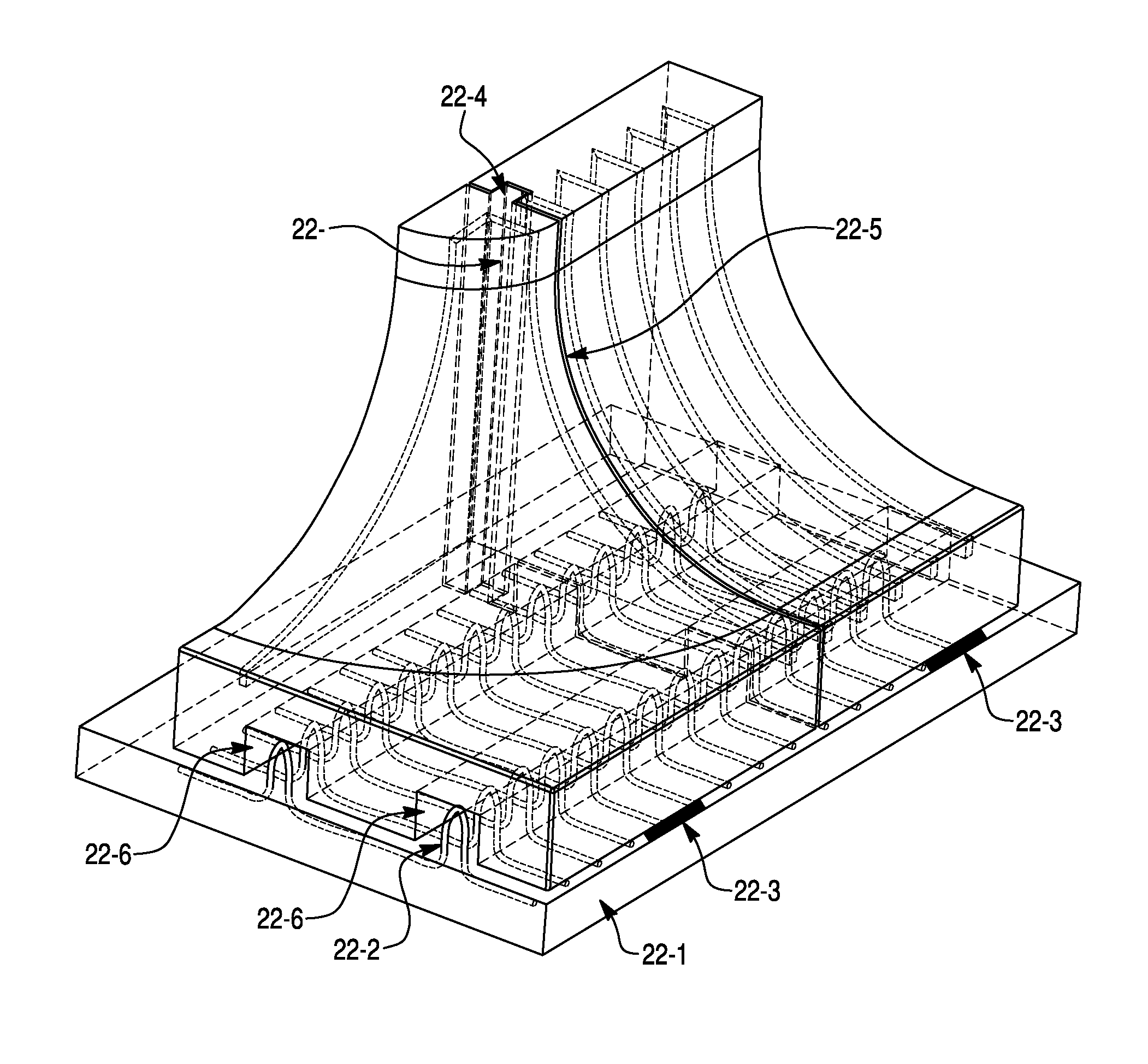
[0037]Since bridge piers and abutments are the most common hydraulic substructures, in the following description we use bridge piers and an abutment as examples for proof of concept; the local vortex preventing scour countermeasure technique described here can be extended to other hydraulic substructures.

[0038]A global view of the invention and its components is shown in FIGS. 5 and 6 for bridge piers and an abutment. FIG. 7 contains a detailed view of the vortex generator devices used in the invention. The components include:[0039]1. Hyper-ellipse convex-concave bridge pier or abutment fairing nose[0040]2. Faired prismatic apron[0041]3. Specially designed vortex generators[0042]4. Hyper-ellipse downstream fairing[0043]5. Faired elliptical pier or abutment nose[0044]6. Existing bridge pier or abutment[0045]7. Interlocking key between sections of the fairing[0046]8. Faired elliptical pier downstream surface[0047]9. Existing or faired circular pier nose[0048]3a. Vortex generator assem...


PUM


Abstract

Disclosed is a manufactured three-dimensional convex-concave fairing with attached vortex generators, for hydraulic structures such as bridge piers and abutments, whose shape prevents the local scour problem around such hydraulic structures. The device is a conventionally made concrete or fiber-reinforced composite, or combination of both, vortex generator equipped hydrodynamic fairing that is fit or cast over an existing or new hydraulic structure around the base of the structure and above the footing. The vortex generators are positioned so as to energize decelerating near wall flow with higher-momentum outer layer flow. The result is a more steady, compact separation and wake and substantially mitigated scour inducing vortical flow.

Description

[0001]This application claims the benefit of U.S. Provisional Ser. No. 61 / 350,149, filed Jun. 1, 2010.FIELD OF THE INVENTION[0002]The invention generally relates to the fields of Civil Engineering, Hydraulic Engineering, and Soil and Water Conservation. More specifically, the invention relates to a manufactured device to prevent scour around hydraulic structures.BACKGROUND OF THE INVENTION[0003]Removal of river bed substrate around bridge pier and abutment footings, also known as scour, presents a significant cost and risk in the maintenance of many bridges throughout the world. Bridge scour at the foundations of bridge piers and abutments is one of the most common causes of highway bridge failures. It has been estimated that 60% of all bridge failures result from scour and other hydraulic-related causes (Jean-Louis Briaud, 2006). In 1973, a study by the US Federal Highway Administration (FHWA) was conducted to investigate 383 bridge failures caused by catastrophic floods, and...

Claims


Application Information

Patent Timeline
Patent Type & Authority Applications(United States)
IPC IPC(8): E02D5/60
CPCE02B3/12E02B3/02E02D5/60
Inventor SIMPSON, ROGER L.LOWE, K. TODDTIAN, QUINN Q.
Owner APPLIED UNIV RES
Why Eureka
Try Eureka