
Active oil-gas separator

A kind of oil and gas separator, active technology, applied in the direction of engine components, machines/engines, mechanical equipment, etc., can solve the problems affecting the normal operation of internal combustion engines, oil loss of internal combustion engine lubricating oil, insufficient internal combustion engine lubricating oil, etc., and achieve good market application prospects , reduce loss, and reduce the overall flow resistance of the structure

Pending Publication Date: 2019-11-26
PINGYUAN FILTER
View PDF0 Cites 13 Cited by
  • Summary
  • Abstract
  • Description
  • Claims
  • Application Information

AI Technical Summary

Problems solved by technology

During the working process of the internal combustion engine, blow-by gas will be generated in the crankcase. If the blow-by gas is not discharged in the crankcase in time, the pressure of the crankcase will be too high, which will affect the normal operation of the internal combustion engine.
[0003] Because the blow-by gas contains oil, colloid and impurities, if it is directly put into the atmosphere, it will cause air pollution and fail to meet the national emission standards; the blow-by gas will cause the lubricating oil of the internal combustion engine to lose oil, resulting in insufficient lubricating oil for the internal combustion engine

Method used


Image

  • Active oil-gas separator
  • Active oil-gas separator
  • Active oil-gas separator

Examples


Embodiment Construction

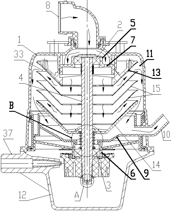
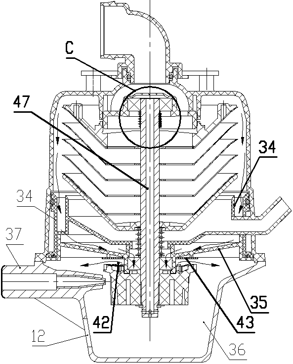
[0055] Such as Figure 1 to Figure 10 As shown, the active oil-gas separator of the present invention includes a housing 1, a central shaft 4 is installed in the housing 1 through an upper bearing 2 and a lower bearing 3, and an oil-gas separation is provided between the middle and upper parts of the central shaft 4 and the housing 1. mechanism, a driving mechanism for driving the rotation of the central shaft 4 is provided between the bottom of the central shaft 4 and the housing 1; the upper bearing 2 is installed on the housing 1 through the upper bearing seat 5, and the lower bearing 3 is installed on the On the shell 1; the upper bearing seat 5 is provided with an installation cavity for accommodating the upper bearing 2, and the upper bearing seat 5 outside the installation cavity is provided with an opening 7 for oil and gas to pass through in the up and down direction;

[0056] The top of the housing 1 is provided with an air inlet 8, and the air inlet 8 communicates w...


PUM


Abstract

The invention discloses an active oil-gas separator which comprises a shell. An oil-gas separation mechanism is arranged between the upper middle portion of a center shaft in the shell and the shell,and a driving mechanism used for driving the center shaft to rotate is arranged between the bottom of the center shaft and the shell. An air inlet used for introducing fleeing gas of an internal combustion engine is formed in the top of the shell, a pure gas outlet is formed in the position, at the bottom of the oil-gas separation mechanism, of the side wall of the shell, and an oil return openingused for lubricating oil to flow out is formed in the position, below the driving mechanism, of the side wall of the shell. The oil-gas separation mechanism comprises a separation disc upper end cover, a separation disc lower end cover and all middle separation discs which are connected between the separation disc upper end cover and the separation disc lower end cover and are arranged on the center shaft. The active oil-gas separator begins to work automatically after a motor vehicle is ignited and stops working automatically after the flameout, electric control is not needed in the work process, efficient oil-gas separation can be conducted on engine fleeing gas, losses of lubricating oil are reduced, long-term stable running can be achieved without maintenance, and very high market value is achieved.

Description

technical field [0001] The invention relates to the technical field of machinery, in particular to the oil-gas separation technology of an internal combustion engine. Background technique [0002] The lower part of the crankcase of the internal combustion engine is provided with an oil pan, and the upper part is provided with an upper cover. During the working process of the internal combustion engine, blow-by gas will be generated in the crankcase. If the blow-by gas is not discharged in the crankcase in time, the pressure of the crankcase will be too high, which will affect the normal operation of the internal combustion engine. [0003] Because the blow-by gas contains oil, colloid and impurities, if it is directly put into the atmosphere, it will cause air pollution and fail to meet the national emission standards; the blow-by gas will cause the lubricating oil of the internal combustion engine to lose oil, resulting in insufficient lubricating oil for the internal combu...

Claims


Application Information

Patent Timeline
Patent Type & Authority Applications(China)
IPC IPC(8): F01M13/04
CPCF01M13/04F01M2013/0422
Inventor 韩磊黄军王营军任志学于立业王飞跃
Owner PINGYUAN FILTER
Learn More