
Combined fan

A combined and fan technology, applied in non-variable-capacity pumps, gear transmissions, friction transmissions, etc., can solve the problems of inflexible blowing range of tower fans, and achieve small occupied space, large opening angle, and enhanced stability. Effect

Pending Publication Date: 2019-11-26
GREE ELECTRIC APPLIANCES INC
View PDF0 Cites 1 Cited by
  • Summary
  • Abstract
  • Description
  • Claims
  • Application Information

AI Technical Summary

Problems solved by technology

[0005] Therefore, the technical problem to be solved by the present invention is to overcome the defect that the blowing range of the tower fan in the prior art is not flexible enough, thereby providing a combined fan

Method used


Image

  • Combined fan
  • Combined fan
  • Combined fan

Examples


Embodiment

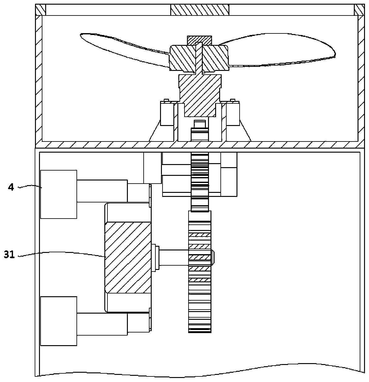
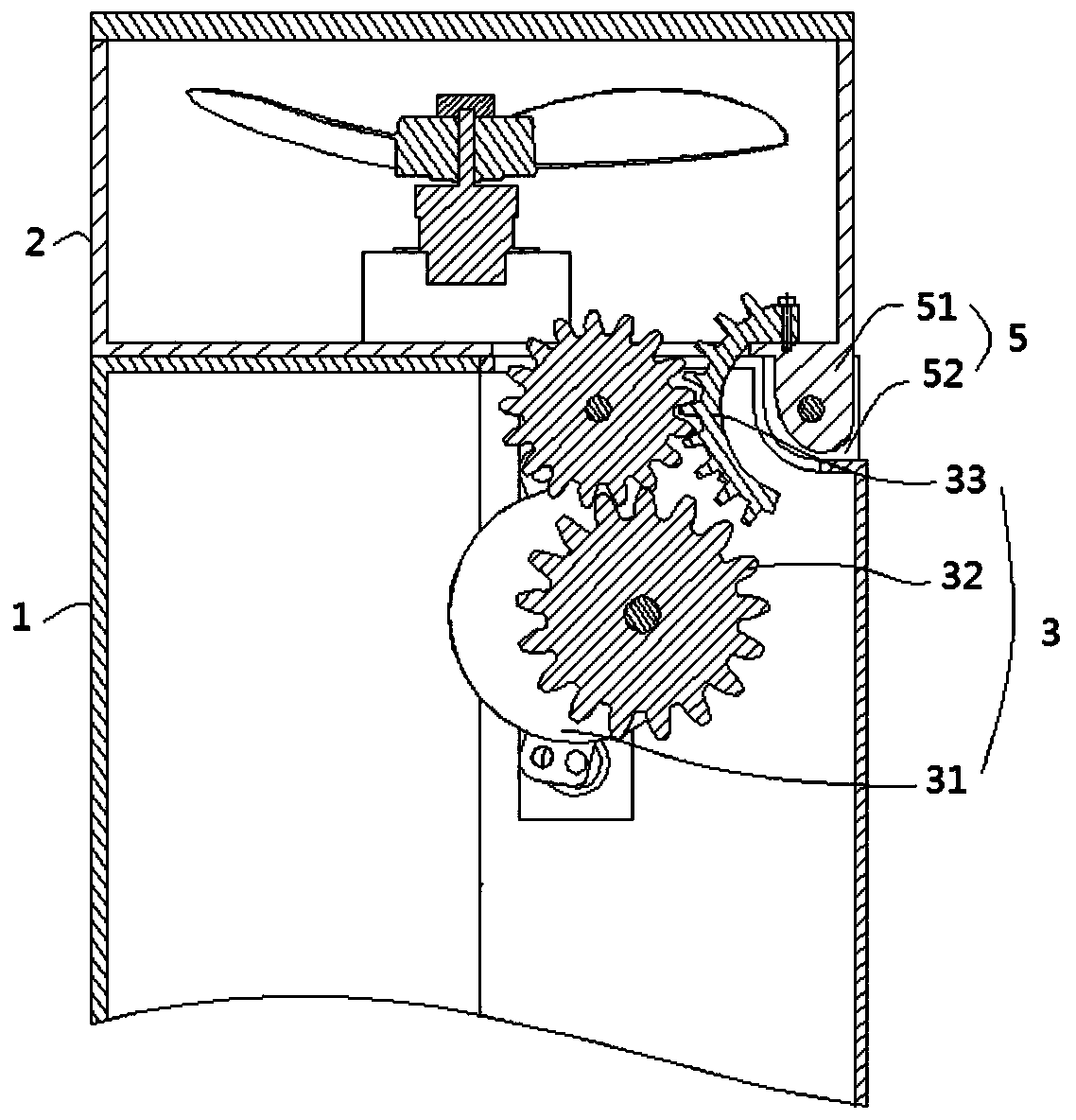
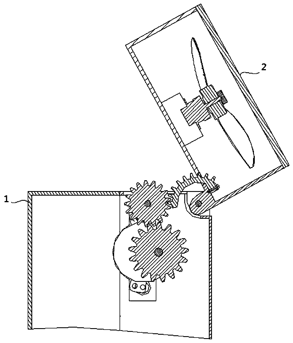
[0042] Figure 1 to Figure 5 As shown, a combined fan provided for this embodiment includes: a tower fan body 1; a rotating fan 2 hinged on the upper end surface of the tower fan body 1; and a drive assembly 3 arranged in the tower fan body 1, which The driving end acts on the rotating fan 2 to drive the rotating fan 2 to rotate; wherein the driving assembly 3 includes: a motor 31 arranged inside the tower fan body 1; a gear set 32 ​​arranged inside the tower fan body 1 and connected with the motor 31 The gears of the motor mesh in turn; the rack 33 is arranged on the rotating fan 2 and meshes with the gear set 32 ​​.

[0043]The rotating fan 2 in this embodiment is a commonly used axial flow fan, which has a simple structure and low cost, and is easy to select and install because of its mature technology.

[0044] Of course, in some other implementation manners, the above-mentioned rotating fan 2 may also be a bladeless fan or the like.

[0045] It should also be noted that...


PUM


Abstract

The invention provides a combined fan. The combined fan comprises a tower fan body, a rotating fan and a drive assembly arranged in the tower fan body, wherein the rotating fan is hinged to the upperend face of the tower fan body; the drive end of the drive assembly acts on the rotating fan to drive the rotating fan to rotate; the drive assembly comprises a motor arranged inside the tower fan body, a gear set arranged inside the tower fan body and meshed with the motor gear of the motor in sequence and a rack which is arranged on the rotating fan and meshed with the gear set. The rotating fanis hinged to the upper end of the tower fan body, and an air port of the rotating fan can rotate relative to the tower fan body under the action of the drive component, so that the air outlet angle is changed, the air outlet range is increased, and especially in the height direction, and the problem that the air outlet range of the original tower fan is not flexible enough is solved.

Description

technical field [0001] The invention relates to the technical field of household appliances, in particular to a combined fan. Background technique [0002] The tower fan "throws" the wind out through the cross-flow fan to form an airflow—the wind pressure is generated by the rotation of the wind wheel to generate centrifugal wind force, and finally the wind force is transmitted out through the internal air guide wall. Since the cross-flow wind wheel is generally cylindrical, the tower fan is used to obtain a three-dimensional air flow wall, or "air curtain", which is perpendicular to the ground and blows from side to side. In addition, the cross-flow wind wheel has many blades, so the air supply is uniform and soft, which is very close to the natural wind, so it is deeply loved by consumers for its soft wind. [0003] Among them, the use environment of the tower fan is mostly the living room of the consumer. In this environment, the consumer is mostly in a sitting or lying ...

Claims


Application Information

Patent Timeline
Patent Type & Authority Applications(China)
IPC IPC(8): F04D25/16F04D25/10F04D29/00F16H1/08F16H19/04
CPCF04D25/166F04D25/105F04D29/002F16H1/08F16H19/04
Inventor 张培德丁睿徐余良陈正超陈志聪梁健华
Owner GREE ELECTRIC APPLIANCES INC
Learn More