[0029] The technical solutions in the embodiments of the present invention will be clearly and completely described below in conjunction with the accompanying drawings in the embodiments of the present invention. Obviously, the described embodiments are only a part of the embodiments of the present invention, rather than all the embodiments. Based on the embodiments of the present invention, all other embodiments obtained by those of ordinary skill in the art without creative work shall fall within the protection scope of the present invention.
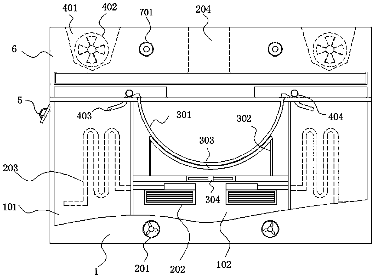
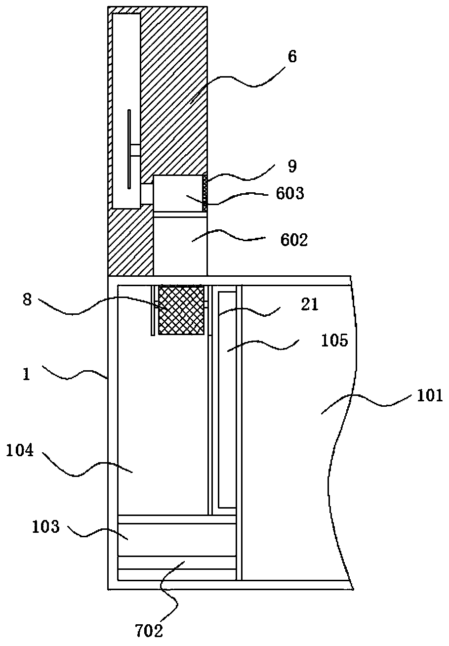
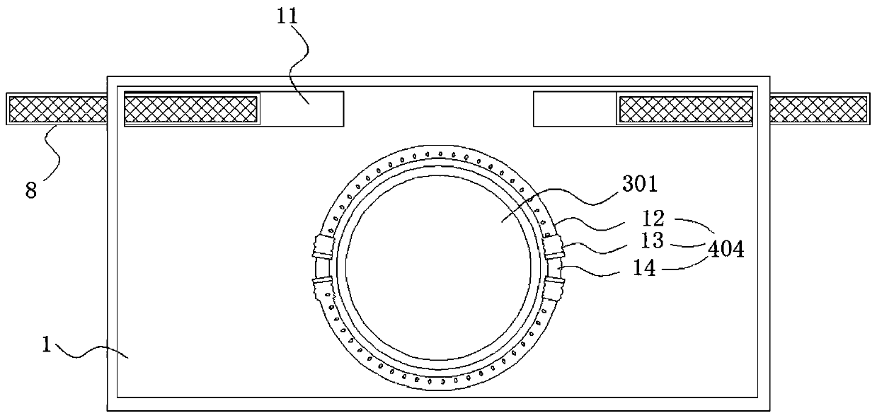
[0030] See Figure 1-6 , An energy-saving and environmentally-friendly large pot stove, comprising a stove top 1, a vertical plate 6, a cast iron pot 301 arranged in the middle of the countertop of the stove 1, and an oil fume assembly. The inner middle of the stove 1 is a working room 102 and a working room 102 A heating mechanism for heating the cast iron pot 301 is installed inside, and an installation room 103 is provided at the bottom of the cooktop 1 on both sides of the working room 102. The installation room 103 is used to install the pipeline used in the device, which is convenient for installation and use.
[0031] The stovetop 1 is also provided with a residue collection chamber 104, the top plate of the stovetop 1 is provided with a residue collection hole 11 communicating with the residue collection chamber 104, and the lower port of the residue collection hole 11 is provided with a drain box capable of drawing out the residue collection chamber 104 8. The vertical plate 6 is vertically arranged on the top surface of the stove 1 and covers the slag collecting hole 11, and a side of the vertical plate 6 close to the cast iron pot 301 is provided with a slag discharge port 602 communicating with the slag collecting hole 11. 6 is also provided with a smoke exhaust cavity 401, which communicates with the outside world. Two splints are arranged longitudinally in the remnant chamber 104, and a chute is set on the inner side of the two splints. The drain box 9 is located between the two splints and is drained. The outer wall of the box 8 is provided with a sliding block. The through-hole sliding groove of the drain box 8 is slidingly arranged between the two splints. The drain box collects the garbage cleaned from the stove, and the dirty water enters the collection room 104 , And the bottom of the stove 1 is provided with a sewage pipe communicating with the residue collection chamber 104.
[0032] The range hood assembly includes a range hood 402, a range hood 403, and a range hood mechanism 404 located outside the cast iron pot 301, and the range hood 402 is arranged in the exhaust cavity 401.
[0033] The oil fume suction mechanism 404 includes a hard tube 12, a hose 13, and a connecting tube 14. The connecting tubes 14 are symmetrically arranged on the top surface of the cooktop 1 on both sides of the cast iron pot 301, and the hard tube 12 is arc-shaped and tubular, and Both ends of the hard tube 12 are connected to the hose 13, and the two ends of the hard tube 12 are connected to the two connecting tubes 14 through the hose 13 respectively. The hard tube 12 is provided with through holes for absorbing oil fume, and the hard tube 12 Equipped with oil fume filter element, the oil fume filter element can adopt the roll-shaped oil fume filter cotton arranged in the hard tube 12, which is low in price and easy to replace.
[0034] The oil fume conveying pipe 403 is arranged in the cooktop 1 and communicates with the connecting pipe 14. The other end of the oil fume conveying pipe 403 is connected to the inside of the smoke exhaust chamber 401; the range hood 402 works and absorbs the production in the cast iron pot 301 through the range hood The oil fume is then transported into the fume exhaust chamber 401 through the oil fume delivery pipe 403 to be discharged.
[0035] Further, the cooktop 1 is provided with a water storage chamber 101, the back of the vertical plate 6 is provided with a rectangular groove 601, a row of first guide wheels 704 is fixed on the top of the bottom surface of the groove 601, and the bottom surface of the groove 601 A row of second guide wheels 705 is slidably connected at the bottom, and a rubber tube 703 is also arranged in the groove 601. The rubber tube 703 is spirally wound around the first guide wheel 704 and the second guide wheel 705, and the first guide wheel 704 and the second guide wheel 705 are both located inside the bend of the rubber tube 703. The water outlet end of the rubber tube 703 passes through the vertical plate 6 and is connected with a sprinkler 701. The water inlet end of the rubber tube 703 extends into the cooktop 1. It is connected to the inside of the water storage chamber 101. A water pump is installed between the rubber tube 703 and the pipeline of the water storage chamber 101. The water pump is used to pump out the water in the water storage chamber 101, and then reaches the spray head through the rubber tube 703 to spray out. It is convenient to clean the stove 1 and the cast iron pot 301, and because the rubber tube 703 is movable in the groove, it is convenient to pull the nozzle 701, so as to wash the surface of the stove 1 in all directions and flush the garbage on the stove 1 Into the slag discharge port 602 on the vertical plate 6, so that the garbage enters the drain box 8, and the dirty water enters the residue collection chamber.
[0036] Further, the second guide wheel 705 includes a limiting plate 16, a roller 17, a middle column 18, and a connecting column 19. The middle column 18 is sheathed with a roller 17 and one end of the middle column 18 is fixedly connected to the connecting column 19. The limiting plate 16 is fixed at the other end of the middle column 18, the end of the connecting column 19 is connected with a sliding block 20, the bottom surface of the groove 601 is longitudinally provided with a sliding groove 15 that is slidably fitted with the sliding block 20, and the rubber tube 703 Wound on the outside of the drum 17, the end of the rubber tube 703 extends upward and passes through the vertical plate 6; it is convenient to pull the rubber tube 703 so that the rubber tube 703 is arranged in an orderly manner in the groove 601, which is convenient for use and convenient for the device Install it close to the wall.
[0037] Further, the heating mechanism includes a fixing frame 302, a heating coil 303, and a cooling fan 304. The fixing frame 302 is fixed in the working room 102, and the heating coil 303 is installed on the top of the fixing frame 302 and used for heating the cast iron pot 301 and cooling The fan 304 is arranged at the bottom of the fixed frame 302 for cooling the heating coil 303; the structure is simple and easy to use.
[0038] Further, an exhaust pipe 202 is provided in the working room 102, and a heat exchange chamber 105 is provided inside the cooktop 1 adjacent to the water storage chamber 101, and the heat exchange chamber 105 is provided with an air outlet with the exhaust pipe 202. Spiral heat exchange tube 203 connected at the end, the vertical plate 6 is provided with an exhaust port 204, and an exhaust fan is provided in the exhaust port 204. The air outlet end of the spiral heat exchange tube 203 is connected to the exhaust port 204, An exhaust fan 201 connected to the working chamber 102 is arranged on the side plate; the spiral heat exchange tube 203 passes through the heat exchange chamber 105, thereby heating the water in the water storage chamber 101, and orderly using the waste heat in the stove to make the water storage chamber The moisture in 101 is more comfortable.
[0039] Further, the heat exchange chamber 105 is provided with a layer of heat insulation layer 21 except for the inner wall of the water storage chamber 101, so that the heat in the heat exchange chamber 105 can be concentrated and converted into the water storage chamber 101.
[0040] Further, the top plate of the cooktop 1 is provided with threaded holes symmetrically, and the outer side of the connecting pipe 14 is fixed with a cannula connected to the inside, and the outer wall of the cannula is provided with an external thread that matches with the threaded hole. , The connecting pipe 14 is fixed by fitting a threaded hole with a cannula, and the air inlet end of the oil fume conveying pipe 403 communicates with the threaded hole; it is convenient to install and disassemble the connecting pipe 14 so as to facilitate cleaning or replacement of the oil fume suction mechanism.
[0041] Further, the side plate of the cooktop 1 is provided with a notch communicating with the remnant chamber 104, and the cover 5 is hinged at the notch, and the cover 5 is opened, so that the drain box 8 can be easily drawn out.
[0042] Further, a fume inlet 603 is provided on the side of the vertical plate 6 close to the cast iron pot 301, the fume inlet 603 is connected to the fume exhaust chamber 401, and the air inlet port of the fume inlet 603 is provided with a filter 9; further improving the effect of fume absorption .
[0043] When the present invention is in use, it is normally energized. After the heating coil 303 is energized, the cast iron pot 301 is heated, and the range hood 402 works, thereby absorbing most of the lampblack through the lampblack mechanism, and the through hole on the lampblack hard tube 12 enters the lampblack mechanism , The oil fume is filtered by the oil fume filter element, and then enters the fume exhaust chamber 401 through the oil fume conveying pipe 403. Part of the oil fume can also be absorbed through the oil fume inlet 603. After use, manually hold the sprinkler and open the connection rubber tube 703 and the water storage chamber 101 water pump, so that the sprinkler 701 is used to wash the stove 1, sewage and garbage enter the collection chamber 104 through the slag discharge port 602, so that the garbage enters the drain box 8, and the dirty water enters the collection chamber In 104, the drain box 8 is regularly drawn out, and the garbage in the drain box 8 is processed, and the waste collection room discharges the sewage through the sewage pipe.
[0044] Although the embodiments of the present invention have been shown and described, those of ordinary skill in the art can understand that various changes, modifications, and substitutions can be made to these embodiments without departing from the principle and spirit of the present invention. And variations, the scope of the present invention is defined by the appended claims and their equivalents.