Textile cloth drying equipment

A technology for drying equipment and textile fabrics. It is applied in the direction of drying solid materials, drying chamber/container, and drying gas arrangement. It can solve the problems of low drying efficiency and large water vapor, and achieve the effect of speeding up drying and ensuring power transmission.

Inactive Publication Date: 2019-11-26
单东霞
View PDF4 Cites 3 Cited by
  • Summary
  • Abstract
  • Description
  • Claims
  • Application Information

AI Technical Summary

Problems solved by technology

[0002] In textile operations, drying cloth is a very important link. Traditional drying has low drying efficiency and large water vapor, so this textile cloth drying equipment is designed.

Method used


Image

  • Textile cloth drying equipment
  • Textile cloth drying equipment
  • Textile cloth drying equipment

Examples


specific Embodiment approach 1

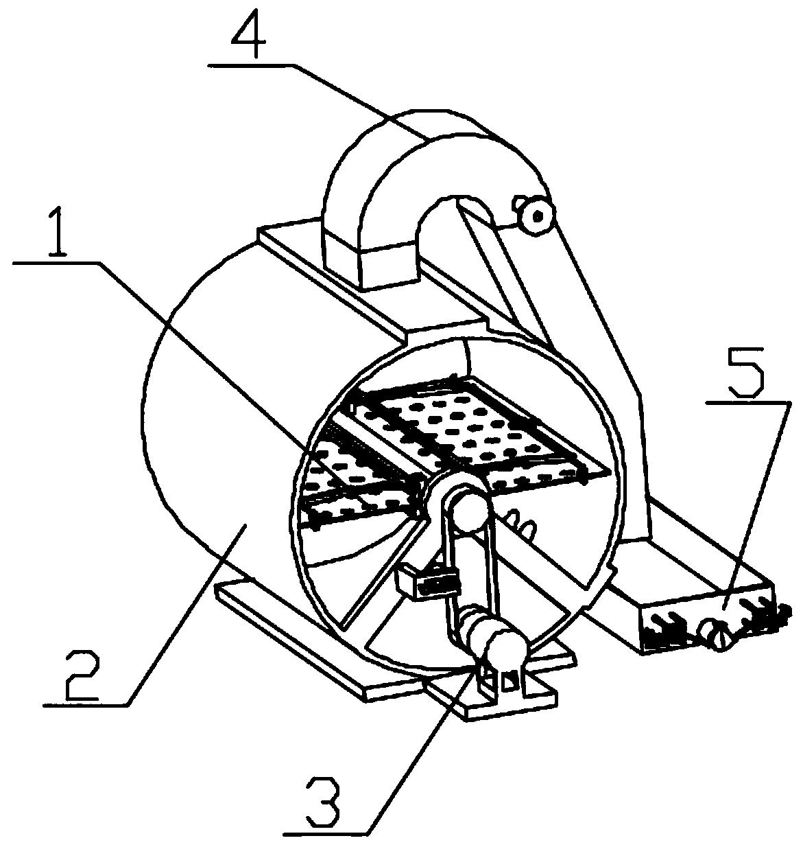
[0041] Combine below figure 1 , figure 2 , image 3 , Figure 4 , Figure 5 , Figure 6 , Figure 7 , Figure 8 , Figure 9 , Figure 10 , Figure 11 , Figure 12 , Figure 13 , Figure 14 , Figure 15 , Figure 16 , Figure 17 , Figure 18 , Figure 19 , Figure 20 , Figure 21 , Figure 22 , Figure 23 Describe this embodiment, the present invention relates to a kind of drying equipment, more specifically a kind of drying equipment for textile fabrics, including a cloth clamping frame mechanism 1, a body mechanism 2, a power tensioning mechanism 3, a liquid cooling tube mechanism 4, a set The liquid tank mechanism 5, the equipment can accelerate the drying of the cloth, the equipment can ensure the transmission of power, the equipment can guide and cool the water vapor into water for collection, and the equipment can automatically release the water.

[0042] The connection mode between the cloth clamping frame mechanism 1 and the fuselage mechanism 2 is...

specific Embodiment approach 2

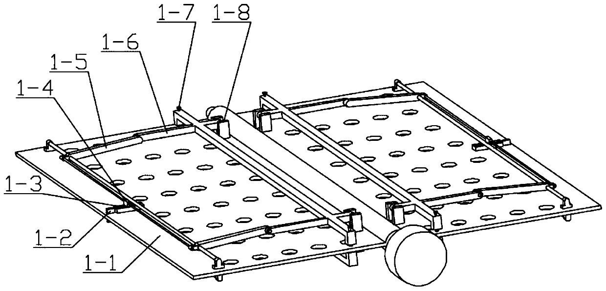
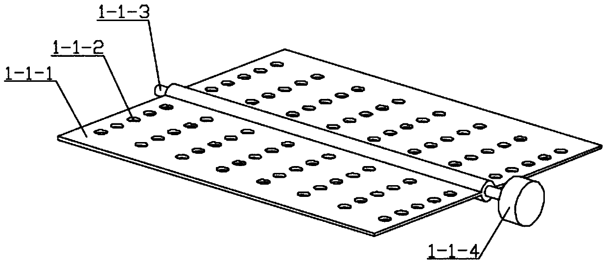
[0044] Combine below figure 1 , figure 2 , image 3 , Figure 4 , Figure 5 , Figure 6 , Figure 7 , Figure 8 , Figure 9 , Figure 10 , Figure 11 , Figure 12 , Figure 13 , Figure 14 , Figure 15 , Figure 16 , Figure 17 , Figure 18 , Figure 19 , Figure 20 , Figure 21 , Figure 22 , Figure 23 Describe this embodiment, this embodiment will further explain the first embodiment, the cloth clamping frame mechanism 1 includes a frame body mechanism 1-1, a waterproof cover mechanism 1-2, a cloth clamping driving mechanism 1-3, and a cloth clamping linkage mechanism 1-4, edge pressing seat mechanism 1-5, intermediate pressing mechanism 1-6, spring pressing seat mechanism 1-7, hinged seat 1-8, frame body mechanism 1-1 is connected with waterproof cover mechanism 1-2, waterproof The connection mode between the cover mechanism 1-2 and the cloth clamping driving mechanism 1-3 is bearing connection, the cloth clamping driving mechanism 1-3 cooperates with...

specific Embodiment approach 3

[0046] Combine below figure 1 , figure 2 , image 3 , Figure 4 , Figure 5 , Figure 6 , Figure 7 , Figure 8 , Figure 9 , Figure 10 , Figure 11 , Figure 12 , Figure 13 , Figure 14 , Figure 15 , Figure 16 , Figure 17 , Figure 18 , Figure 19 , Figure 20 , Figure 21 , Figure 22 , Figure 23Describe this embodiment, this embodiment will further explain the first embodiment, the fuselage mechanism 2 includes a negative pressure fan mechanism 2-1, a cylindrical fuselage 2-2, a connecting seat 2-3, and a bearing seat A2-4 , permeable hole 2-5, negative pressure fan mechanism 2-1 is connected with cylindrical body 2-2, connecting seat 2-3 is connected with cylindrical body 2-2, bearing seat A2-4 is connected with connecting seat 2-3 Connected, the permeable hole 2-5 is opened on the cylinder body 2-2; the negative pressure fan mechanism 2-1 includes a fan motor 2-1-1, a fan coupling 2-1-2, a ring plate 2-1- 3. Negative pressure blade 2-1-4, fan ...


PUM


Abstract

The invention relates to drying equipment, in particular to textile cloth drying equipment. The textile cloth drying equipment comprises a cloth clamping rack mechanism, a machine body mechanism, a power tensioning mechanism, a hydraulic cooling pipe mechanism and a liquid collection tank mechanism; the equipment can be used for clamping cloth, can quicken drying of the cloth, can guarantee the transmission of power, can guide and cool water steam into water and collect the water and can automatically drain the water; the cloth clamping rack mechanism is connected with the machine body mechanism by a bearing; the machine body mechanism is connected with the power tensioning mechanism and the hydraulic cooling pipe mechanism; and the liquid collection tank mechanism is connected with the machine body mechanism.

Description

technical field [0001] The invention relates to a drying device, more specifically a textile cloth drying device. Background technique [0002] In textile operations, drying cloth is a very important link. Traditional drying has low drying efficiency and large water vapor, so this textile cloth drying equipment is designed. Contents of the invention [0003] The technical problem mainly solved by the present invention is to provide a textile cloth drying equipment, which can clamp the cloth, speed up the drying of the cloth, ensure the transmission of power, guide the water vapor to cool into water for collection, and The water is released automatically. [0004] In order to solve the above technical problems, the present invention relates to a drying equipment, more specifically a drying equipment for textile fabrics, including a cloth clamping frame mechanism, a fuselage mechanism, a power tensioning mechanism, a liquid cooling tube mechanism, and a liquid collection ta...

Claims


Application Information

Patent Timeline
Patent Type & Authority Applications(China)
IPC IPC(8): F26B11/18F26B21/00F26B23/06F26B25/00F26B25/02F26B25/18
CPCF26B11/18F26B21/004F26B23/06F26B25/00F26B25/02F26B25/18
Inventor 单东霞林立
Owner 单东霞
Why Eureka
Try Eureka