Robot control system and method

A control system and robot technology, applied in the direction of program control of manipulators, manipulators, manufacturing tools, etc., can solve the problems of complex environment, large floor area, huge financial resources, manpower and time, so as to reduce workload, improve satisfaction, Optimize the effect of travel experience

Inactive Publication Date: 2019-11-29
HEFEI UNIV OF TECH
7 Cites 2 Cited by

AI-Extracted Technical Summary

Problems solved by technology

[0003] Considering that large airports at home and abroad generally occupy a large area and the environment is relatively complex,...

Method used

As shown in Figure 4-8, in the present embodiment, described drive unit 70 comprises motor 72, motor governor 72 and encoder, and described encoder is installed on described motor 72, and with described The motor governor 72 is connected in communication, and the motor governor 72 is connected in communication with the motion control unit 20, and is used to receive the rotation speed of the omnidirectional wheel 822 (moving wheel), steering, etc. transmitted by the motion control unit 20. data signal, the motor governor 72 converts the rotational speed steering signal of each wheel into a corresponding pulse width modulation (PWM) signal to drive the motor 72 to rotate, and then drives the action of the omnidirectional wheel 822 through the transmission structure connected with the output shaft of the motor 72, Thus realizing the movement of the robot. The motor drive control process of the robot is shown in Figure 9. In this embodiment, the motor governor 72 performs closed-loop speed control on the motor 72, and the encoder feedback signal (encoder measured speed value) and the motion control unit 20 The preset speed value sent is compared, and the adjusted PWM drive signal is obtained through the control algorithm in the motor governor 71 an...

Abstract

The invention provides a robot control system and method. The robot control system comprises a robot body, a central control unit, a motion control unit and a visual guide unit. The robot body comprises a driving unit. The motion control unit is arranged on the robot body and is in communication connection with the central control unit and the driving unit. The motion control unit is used for receiving a first control instruction from the central control unit to control the work mode of the robot and the pose, moving and steering of a movable platform. The visual guide unit is connected with the motion control unit and used for acquiring colored tape track information on the preset motion track of the robot and transmitting the acquired colored tape track information to the motion controlunit. The motion control unit controls the robot to move along the track according to the received colored tape track information. By means of the robot control system and method, the practical valueand service quality of the robot can be improved, and manpower and material resources are saved.

Application Domain

Programme-controlled manipulator

Technology Topic

Movement controlRobot control system +6

Image

  • Robot control system and method
  • Robot control system and method
  • Robot control system and method

Examples

  • Experimental program(1)

Example Embodiment

[0038] The following describes the implementation of the present invention through specific specific examples. Those skilled in the art can easily understand other advantages and effects of the present invention from the content disclosed in this specification. The present invention can also be implemented or applied through other different specific embodiments, and various details in this specification can also be modified or changed based on different viewpoints and applications without departing from the spirit of the present invention.
[0039] See Figure 1-14. It should be noted that the illustrations provided in this embodiment only illustrate the basic idea of ​​the present invention in a schematic way, and the figures only show the components related to the present invention instead of the number, shape, and shape of the components in actual implementation. For size drawing, the type, quantity, and proportion of each component can be changed at will during actual implementation, and the component layout type may also be more complicated.
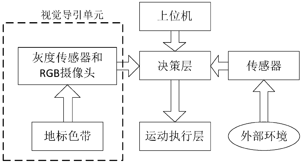
[0040] Such as Figure 1-2 As shown, the embodiment of the present invention discloses a robot control system. The robot control system includes a robot body, and a central control unit 60 (upper computer 63 and remote control device) arranged on the robot body, a motion control unit 20, and a vision guide The unit 40 and the driving unit 70 for driving the robot moving wheels; the robot body includes the driving unit 70 for driving the robot moving wheels. The robot control system can be used to control airport service robots, which can be used for security inspections and human-machine interaction functions. The control system enables the airport service robots to work in a designated working area, that is, the airport terminal Complete some designated functions, that is, guide passengers, provide airport information inquiries and conduct security inspections. The detailed control principles are described in the following.
[0041] figure 1 The information transmission process of the control system of this embodiment is shown. The control system collects landmark ribbon information in real time through the vision guidance system and transmits it to the motion control unit 20, and collects and transmits external environmental information through sensors such as the gyroscope 81 and the laser TOF rangefinder 51 that will be described later. To the motion control unit 20, the motion control unit 20 as a decision-making layer responds to the external request sent by the central control unit 60 (upper computer 63 and remote control device) in real time, processes the data to make decisions, and transmits the instructions to the execution modules of the robot to achieve Control of the robot. It should be noted that the sensors that collect external environmental information may also include temperature sensors, smoke sensors, and so on.
[0042] It should be noted that in this embodiment, the robot has two motion modes, which are a remote sensing movement instruction mode (controlled by a remote control device) or a trajectory tracking mode.
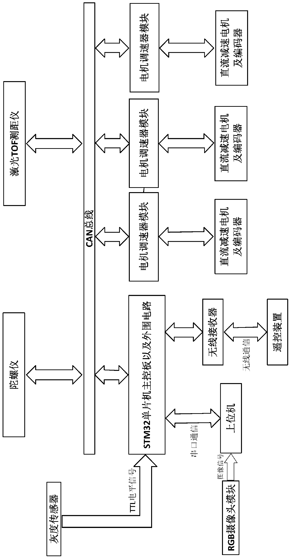
[0043] figure 2 Shows the overall system block diagram of the robot control system of the present invention. The motion control unit 20 (STM32 single-chip microcomputer main control board 21 and peripheral circuits) uses serial port communication for data transmission between the PC and the upper computer 63. The serial port is dedicated to The point-to-point two-way communication between the serial port of the PC and the host computer 63 and the device, and the communication mode between the motion control unit 20 and the motor speed controller 71, the gyroscope 81 and the TOF rangefinder 51 is the CAN bus 31 communication. The wireless communication between the motion control unit 20 and the remote control device is realized by using a wireless communication module (wireless receiver), wherein the CAN bus 31, the serial port, and the wireless communication module 32 together constitute the communication unit of the robot control system. As an example, the wireless communication between the motion control unit 20 and the remote control device is realized by using a 2.4G wireless communication module.
[0044] Specifically, in this embodiment, in the communication system of the upper computer 63, a tablet computer equipped with the win10 operating system is used to complete the human-computer interaction function of the airport service through the upper computer 63. The PC and the COM port of the upper computer 63 The level conversion is realized through the USB to TTL transfer module, and then serial communication with the USART of the STM32 single-chip microcomputer main control board 21 is realized, data communication with it, motion control command transmission, etc., to control the movement of the robot.
[0045] Specifically, in this embodiment, for example, the NRF24L01 chip can be selected to realize the communication function between the remote control device and the single-chip main control board 21. All the configuration work of the chip is completed through SPI. The single-chip main control board 21 can, for example, use NRF24L01 digital The output port (IRQ pin) judges the completion of data transmission and reception.
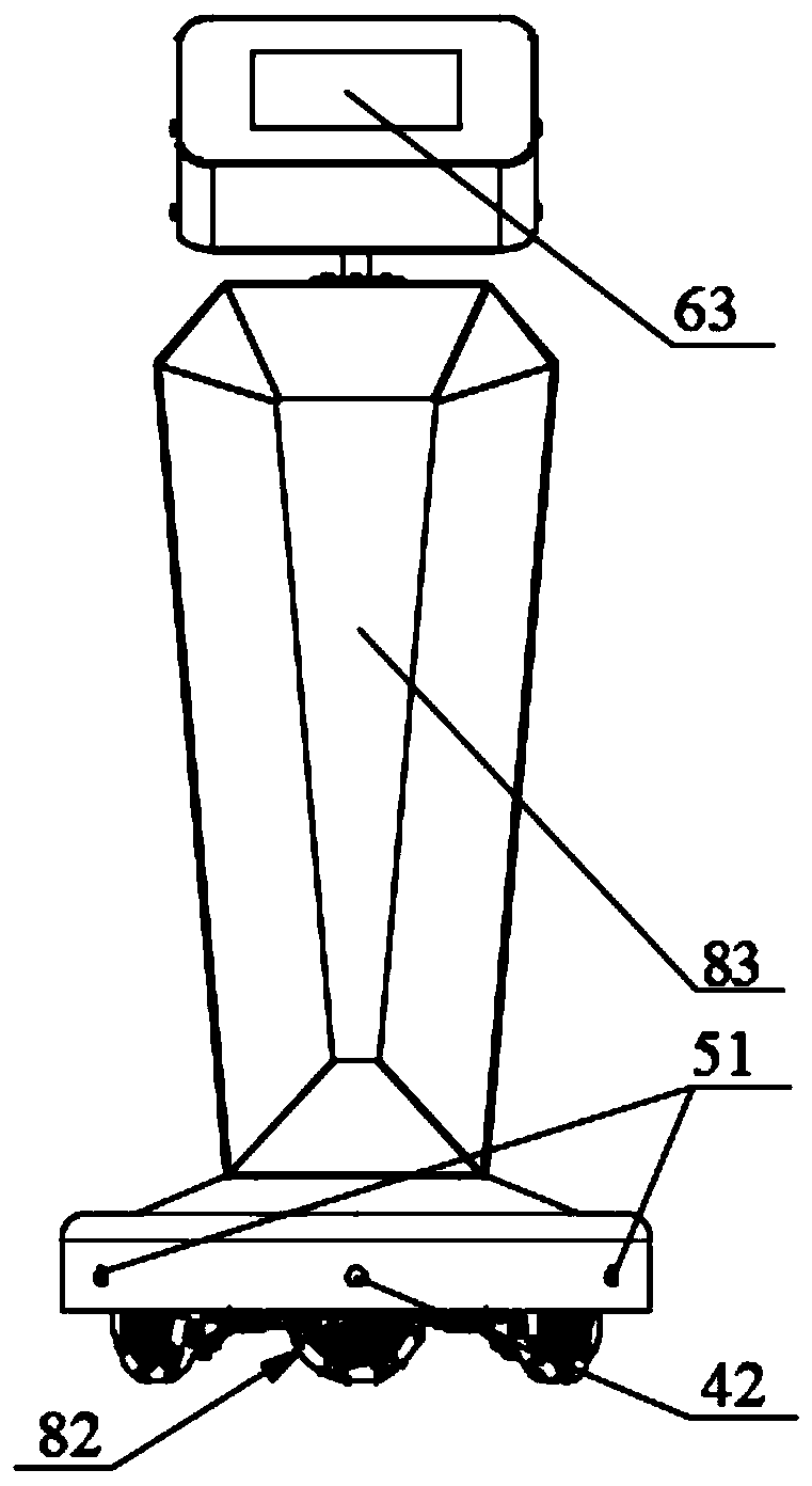
[0046] Such as Figure 3-8 As shown, in this embodiment, the robot body includes a housing frame 83, a drive unit 70, and a mobile wheeled structure 82, wherein the mobile wheeled structure 82 and the drive unit 70 together constitute the movement of the robot Platform, the structure diagram of the mobile platform is as Figure 3-8 Shown
[0047] Such as Figure 4-8 As shown, the housing frame 83 is installed above the movable wheel structure 82, that is, the movable wheel structure 82 is located at the bottom of the housing frame 83, and the movable wheel structure 82 includes a plurality of omnidirectional wheels. 822 (that is, moving wheels), a number of transmission mechanisms 823, a platform chassis 821, and a number of suspension mechanisms 824. A number of the omnidirectional wheels 822 are distributed along the periphery of the platform chassis 821, and one of the omnidirectional wheels 822 passes through a The suspension mechanism 824 is connected and fixed to the platform chassis 821, and the axle of the omnidirectional wheel 822 is connected to the drive unit 70 through a transmission mechanism 823.
[0048] Such as Figure 4-8 As shown, in this embodiment, the omnidirectional wheel 822 may be a double-row continuous switching wheel, for example, the number of the omnidirectional wheel 822 may include three, and its arrangement adopts a three-wheel layout, and three omnidirectional wheels The steering wheel 822 adopts a three-wheeled independent suspension mechanism 824 arranged along the outer edge of the platform chassis 821 on average, with an included angle of 120°, so that the robot can flexibly and stably complete the longitudinal, vertical, and Move in any direction, horizontally and diagonally, so as to realize the function of autonomous inspection.
[0049] Such as Figure 4-8 As shown, in this embodiment, the platform chassis 821 includes an upper chassis 8211, a lower chassis 8213, and a plurality of chassis connecting members 8212, and the upper chassis 8211 and the lower chassis 8213 are connected by a plurality of the chassis connecting members 8212. Such as Figure 4-8 As shown, the upper chassis 8211 and the lower chassis 8213 may be, for example, two equilateral triangular plates that are symmetrically arranged up and down with three apex angles cut off. One end of the hinge plate of the upper chassis 8211 is connected with a frame mounting plate 826 for mounting and supporting the housing frame 83 on the upper surface of the upper chassis 8211 through a number of pillars. The frame mounting plate 826 can also be cut out of three An equilateral triangular plate at the top corner, the triangular plate of the frame mounting plate 826 is coaxially arranged with the triangular plate of the upper chassis 8211 and the triangular plate of the lower chassis 8213, and the triangular plate of the frame mounting plate 826 The upper chassis 8211 and the lower chassis 8213 are offset by a predetermined angle around the three axial directions. In this embodiment, the predetermined angle may be, for example, 60°; the motor 72 of the transmission system is mounted on The lower chassis 8213 is located between the upper chassis 8211 and the lower chassis 8213.
[0050] Such as Figure 4-8 As shown, in this embodiment, the suspension mechanism 824 includes a fixed seat 8243, a shock absorber spring 8242, a shock absorber 8241, a connecting plate, and a hinge plate. The connecting plate includes an upper connecting plate 8246 and a lower connecting plate. 8247, the hinge plate includes two upper hinge plates 8244 and two lower hinge plates 8245; one end of the upper connecting plate 8246 is cut away by the upper hinge plate 8244 and the upper chassis 8211 The edges formed after the top corners are connected, the other end of the upper connecting plate 8246 is connected to the upper end of the bearing support of the omnidirectional wheel 822 through another upper hinge plate 8244; one end of the lower connecting plate 8247 is closed The page plate 824 is connected with the edge formed by cutting off the top corner of the lower chassis 8213, and the other end of the lower connecting plate 8247 is connected to the lower end of the bearing support of the omnidirectional wheel 822 through another lower hinge plate 8245; The fixing seat 8243 is installed and fixed on the upper surface of the upper connecting plate 8246, the shock absorber 8241 is installed and fixed on the surface of the upper chassis 8211 of the platform chassis 821, and the top end of the shock absorber 8241 is higher than the upper surface of the upper chassis 8211. According to the height of the top end of the fixed seat 8243, one end of the shock absorber spring 8242 is hinged with the fixed seat 8243, and the other end of the shock absorber spring 8242 is hinged with the shock absorber 8241.
[0051] Such as Figure 4-8 As shown, in this embodiment, the drive unit 70 includes a motor 72, a motor speed controller 72, and an encoder. The encoder is installed on the motor 72 and is in communication connection with the motor speed controller 72. The motor speed controller 72 is in communication connection with the motion control unit 20, and is used to receive data signals such as the rotation speed and steering of the omnidirectional wheel 822 (moving wheel) transmitted by the motion control unit 20. The motor speed controller 72 The rotation speed signal of each wheel is converted into a corresponding pulse width modulation (PWM) signal to drive the motor 72 to rotate, and then the omnidirectional wheel 822 is driven by the transmission structure connected with the output shaft of the motor 72 to realize the movement of the robot. The motor drive control process of the robot is as follows Picture 9 As shown, in this embodiment, the motor speed controller 72 performs closed-loop speed control on the motor 72, and compares the encoder feedback signal (the encoder measuring speed value) with the preset speed value sent by the motion control unit 20, and the motor The control algorithm and the current limiting module in the speed governor 71 obtain the adjusted PWM drive signal, so as to control the speed of the motor 72 to remain unchanged. The closed-loop speed control can improve the stability and accuracy of the control. As an example, the motor 72 may be, for example, a DC geared motor, the number of the DC geared motors is equal to the number of moving wheels, and the DC geared motor is used to independently drive a moving wheel.
[0052] Such as Figure 4-8 As shown, in this embodiment, the transmission mechanism 823 may adopt, for example, a universal joint coupling. One end of the universal joint coupling is connected to the output shaft of the motor 72 of the drive unit 70, and the other end is connected to The axle of the omnidirectional wheel 822, specifically, the axle of the omnidirectional wheel 822 is connected to the end of the universal joint coupling close to the omnidirectional wheel 822 after passing through the bearing support plate, and the universal joint The coupling can transmit the output torque of the motor 72 of the drive unit 70 to the axle of the omnidirectional wheel 822 to realize power transmission.
[0053] In this embodiment, as Figure 8 As shown, the visual guidance unit 40 is disposed on the robot body, and the visual guidance unit 40 is communicatively connected with the motion control unit 20. The visual guidance unit 40 may include, for example, an optical sensor, a camera, and The landmark ribbon 43 is the preset trajectory of the robot. The robot control system shown detects and judges the relative position of the pre-laid black line (landmark ribbon 43) and the robot itself through the optical sensor and camera installed on the robot mobile platform to realize the tracking of the robot.
[0054] Specifically, such as figure 2 As shown, the camera may be, for example, an RGB camera 42, which is communicatively connected with a host computer 63, and the host computer 63 receives an image of a ground preset color band (landmark color band 43) captured by the RGB camera 42. Perform a series of processing to extract the target ribbon trajectory, output the preset ribbon trajectory information and the current deviation information of the camera relative to the target trajectory to the single-chip main control board 21. The single-chip main control board 21 controls the robot through the preset control program. The movement state of the robot is adjusted to realize the robot's visual guidance function; the processing of the ground preset ribbon image includes image grayscale, Gaussian filtering, Canndy edge detection, Hough Transform, detection of target line, calculation Angular distance and resolution of ribbon area. Such as Figure 7 As shown, the optical sensor may be, for example, a grayscale sensor 41. Several (for example, 15) grayscale sensors 41 are placed on the lower side of the robot moving platform in the forward direction, that is, on the bottom surface of the lower chassis 8213, in a circular shape. Arranged in an arc, each grayscale sensor 41 (infrared pair tube) detects the ground color feature (landmark ribbon 43) directly below it, and transmits the detection signal to the single-chip microcomputer main control board 21 of the motion control unit 20. The main control board 21 calculates and processes the deviation value.
[0055] In this embodiment, the motion control unit 20 is respectively connected to the central control unit 60 and the drive unit 70 in communication, and the motion control unit 20 is used to receive control instructions from the central control unit 60 to control The mobile working mode of the robot, the posture of the mobile platform, the rotation speed and the steering of each mobile wheel. Such as Figure 8 As shown, the motion control unit 20 may include, for example, a single-chip microcomputer and a control program preset on the single-chip microcomputer. The single-chip microcomputer serves as a main control board or a main control board, and the control program is used to implement the single-chip microcomputer and other system units. Communication control and motion control signal analysis and calculation, etc., as an example, for example, the STM32 microcontroller main control board 21 can be selected as the core control unit of the motion control unit 20, and 2 CAN ports and 4 24V power output , 3 12V power outputs, multiple serial communication interfaces, etc. It should be noted that in other embodiments, the number of CAN ports, the number of power outputs, and the number of serial communication interfaces can be designed according to actual needs It is not limited to the enumeration in this embodiment.
[0056] In this embodiment, the design and programming of the robot control system is programmed by C language. The STM32CubeMX platform and MDK5 development software are used to design the software (control program) of the single-chip microcomputer. Use this component to graphically set the chip clock and pins of the STM32 single-chip microcomputer. According to the design of the communication mode of the STM32 single-chip microcomputer main control chip and other functional modules, as well as the performance requirements of the chip, configure the chip pins and clock to complete the serial port , CAN, SPI, AD and other interface channel initialization and other aspects of configuration, after the configuration is completed, use STM32CubeMX to quickly generate the C language engineering framework of the corresponding STM32 microcontroller according to the configuration, and then write the control code in the Keil MDK5 microcontroller application development software project .
[0057] In the CAN bus 31 communication, the schematic diagram of the CAN connection between the motor speed controller 71 and the MCU main control board 21 is as follows: Picture 12 As shown, the single-chip microcomputer main control board 21 (for example, the STM32 single-chip microcomputer main control board 21) provides two CAN ports (CANH and CANL), respectively, with three DC motor speed controllers (the type of the motor speed controller can be RMDS, for example). -108) connection, the MCU main control board 21 integrates the CAN bus 31 interface circuit, the CAN transceiver in the circuit is connected between the CAN controller and the physical bus; the CAN transceiver circuit of the MCU main control board 21 is as attached Figure 13 As shown, the CAN controller and MCP2562-E/MF (CAN transceiver) are connected through CAN1_TX and CAN1_RX interfaces. MCP2562-E/MF converts TTL (Transistor-TransistorLogic, transistor-transistor logic circuit) level signals into CAN standards The differential signal output enables the signal to pass CANH and CANL to be transmitted on two differential voltage bus cables.
[0058] Figure 13 The flow of the control program of the motion control unit 20 in the robot control system is shown. Such as Figure 13 As shown, the control steps of the control program include: first initialize each configuration function in the main function, enter the state of waiting for the control instruction, and enter the corresponding interrupt function after receiving the instruction, and then judge the remote control instruction, enter the remote sensing In the movement instruction mode or the trajectory tracking mode, the rotation speed of the motor is calculated during the operation of the control program to obtain the control signal of the rotation speed, and the motion control unit 20 judges the signal and sends corresponding operation instructions to the driving unit 70.
[0059] Specifically, in the manual remote control mode (remote sensing movement command mode), set the manual remote control mode to the default initial working mode, and after turning on the power supply unit to supply power to the various electrical systems Anyuan, through the remote control device or the motion control interface of the upper computer 63 You can control the movement of the robot. For example, the robot can be moved forward, left, and right through the manual remote control mode, and the general motion mode of the robot can be moved forward, left and right, and the omnidirectional translation mode with the same attitude; the omnidirectional translation operation of the robot can be controlled by the remote control device to control the robot to maintain the attitude The omni-directional plane movement is carried out under changing conditions, that is, the front of the robot will remain facing in one direction during the translation process; the robot can also be controlled to rotate in place through a remote control device. The robot uses a designated function in the microcontroller control program to limit its moving speed to no more than 20m/min. The actual moving speed of the robot can be controlled by the remote control device to vary between 0 and 20m/min. In addition, in this mode, the remote control device or the mode switch button of the host computer 63 can also be used to control the airport service robot to enter the autonomous trajectory tracking mode.
[0060] Specifically, the robot can also enter the trajectory tracking mode through the remote control device or the mode switch button of the mobile debugging interface 62. In this mode, the robot can perceive and recognize the preset color ribbon trajectory on the ground through the camera of the vision guidance system. The gyroscope 81 determines its own posture and realizes trajectory tracking. During the tracking process, the laser rangefinder 51 can sense surrounding obstacles to realize obstacle avoidance, and finally complete the security inspection function. It should be noted that to enable the robot to track the landmark ribbon 43 and move, it needs to be adjusted to manual remote control mode through the remote control device, and the robot is moved to the starting position of the preset trajectory so that the camera can capture the landmark ribbon 43. Then switch to the trajectory tracking mode, the robot can track the target trajectory stably, reach the preset end position, and can react in time when encountering obstacles during the tracking process to avoid collision.
[0061] In this embodiment, as Figure 8 As shown, the robot control system further includes a gyroscope 81 installed on the platform chassis 821, and the gyroscope 81 is communicatively connected with the motion control unit 20, during the movement of the robot The single-chip microcomputer main control board 21 of the motion control unit 20 receives the detection signal of the gyroscope 81 to implement deviation correction.
[0062] In this embodiment, the robot control system further includes a power supply unit 10, which is electrically connected to each power system unit of the robot, and is used to provide the required electric energy for each power system of the robot. . Such as Figure 8 As shown, the power supply unit 10 may include, for example, a battery 11 and a step-down module 12, and the step-down module 12 is configured according to the actual operating voltage of the core device in each power system. As an example, for example, multiple (for example, 6) 3.7V lithium batteries can be connected in series as the power output.
[0063] Such as image 3 with 8 As shown, in this embodiment, in order to realize automatic obstacle avoidance of the robot in the trajectory tracking mode, the robot control system further includes an obstacle avoidance unit 50, which is communicatively connected with the motion control unit 20, The obstacle avoidance unit 50 includes, for example, several laser TOF (Time of flight) rangefinders 51 arranged on the bottom side of the robot and an obstacle avoidance algorithm 52 program stored in the single-chip microcomputer main control board 21 of the motion control unit 20. The rangefinder 51 detects various obstacles or pedestrians encountered on the path of the robot, and transmits the detection signal to the single-chip main control board 21. The single-chip main control board 21 controls the movement of the robot through the obstacle avoidance algorithm to realize the robot's movement. Avoidance. As an example, the laser TOF rangefinder 51 may include, for example, three laser TOF rangefinders, which are arranged on the bottom peripheral edge of the robot on average, and the included angle is 120°. It should be noted that in other embodiments, the number and arrangement position of the TOF rangefinder 51 can also be flexibly set according to actual needs, and is not limited to the list here; in other embodiments, the The obstacle avoidance unit 50 may also be another form of obstacle avoidance unit 50 such as a triangular ranging radar.
[0064] It should be noted that, in this embodiment, the ground preset ribbon image captured by the RGB camera 42 may also be displayed on the mobile debugging interface 6262 of the host computer 63 to facilitate developers to check the ground trajectory tracking situation.
[0065] Such as Figure 8 As shown, in this embodiment, the central control unit 60 includes an upper computer 63 and a service interface 61 and a mobile debugging interface 62 provided on the upper computer 63. among them, Figure 14 The overall function of the built-in software in the upper computer 63 is shown. The software design interface of the airport service platform developed by the upper computer software is divided into a two-level structure. The first-level interface is the main interface window, which mainly provides passengers or staff to find and select the required service interface 61 entrance; mobile debugging interface 62 (status Detection and control) belongs to the second level interface, which is mainly provided to airport staff. Such as Figure 14 As shown, in the service interface 61, the service query content in the service interface 61 includes: flight information query (flight number, airline, timetable), airport service hotline and online consultation, airport traffic query (airport bus , Taxi), shopping, entertainment, and dining around the airport. Such as Figure 14 As shown, in the mobile debugging interface 62, an image frame used to display the image information transmitted by the RGB camera 42 is provided to facilitate developers to view the ground trajectory tracking; in the mobile debugging interface 62, there are serial port selection and baud rate The setting options are convenient for debugging the serial communication with the lower computer (the single-chip main control board 21); the mobile debugging interface 62 is equipped with related mobile control buttons and a display window for the robot operating state parameters. The realization of the mobile buttons is set by each button. Send different information data under serial port communication and send it to the MCU main control board 21 according to the communication protocol, and then control the movement of the robot mobile platform (for example, posture adjustment), and the running state of the robot will also be controlled from the MCU via the serial port The board 21 sends the parameters to the upper computer 63, which is convenient for the staff to view and adjust the robot's posture state by moving buttons.
[0066] Specifically, in the software of the upper computer 63, for example, winform design can be adopted, and the development of robot platform software can be realized in the Microsoft Visual Studio development environment using C# language. The software operating environment is Windows 7 or Windows 10, and the opencv computer vision library is used to process RGB. The path image taken by the camera 42 is used to calculate the trajectory deviation, and the serial port is used to realize the communication between the upper and lower computers. Passengers query relevant airport service information through the airport information query interface (service interface 61) displayed on the host computer 63, and airport security service personnel can view and control the operating status of the robot through the mobile debugging interface 62.
[0067] In this embodiment, as figure 2 As shown, the robot control system also includes a remote control device. The staff can send control instructions to the single-chip microcomputer main control board 21 of the control unit 20 through the remote control device to realize the control of the robot, that is, the robot is working in the remote sensing movement instruction mode.
[0068] It should be noted that in the manual remote control mode (remote sensing movement command mode), the manual remote control mode is set as the default initial working mode. After the power supply unit is turned on to supply power to the various power systems, the remote control device or the upper computer 63 can be moved The debugging interface 62 can control the movement of the robot. For example, the robot can be moved forward, left, and right through the manual remote control mode, and the general motion mode of the robot can be moved forward, left and right, and the omnidirectional translation mode with the same attitude; the omnidirectional translation operation of the robot can be controlled by the remote control device to control the robot to maintain the attitude The omni-directional plane movement is carried out under changing conditions, that is, the front of the robot will remain facing in one direction during the translation process; the robot can also be controlled to rotate in place through a remote control device. The robot uses a designated function in the microcontroller control program to limit its moving speed to no more than 20m/min. The actual moving speed of the robot can be controlled by the remote control device to vary between 0 and 20m/min. In addition, in this mode, the remote control device or the mode switch button of the host computer 63 can also be used to control the airport service robot to enter the autonomous trajectory tracking mode.
[0069] It should be noted that the robot can also enter the trajectory tracking mode through the remote control device or the mode switch button of the mobile debugging interface 62. In this mode, the robot can perceive and recognize the preset ribbon trajectory on the ground through the camera of the vision guidance system , Through the gyroscope 81 to determine its own posture to achieve trajectory tracking. During the tracking process, the laser rangefinder 51 can sense surrounding obstacles to realize obstacle avoidance, and finally complete the security inspection function. It should be noted that in order for the robot to track the landmark ribbon 43 and move, it needs to be adjusted to manual remote control mode, move the robot to the starting position of the preset trajectory, so that the camera can capture the landmark ribbon 43, and then switch to In the trajectory tracking mode, the robot can track the target trajectory stably and reach the preset end position, and can react in time when encountering obstacles during the tracking process to avoid collision.
[0070] It should be noted that the various system units in the robot control system of this embodiment cooperate with each other to realize the robot's omni-directional movement, autonomous inspection, human-computer interaction, information query, airport navigation and other functions, which greatly improves the service quality And security efficiency, effectively provide passengers with comprehensive and thoughtful services, reduce the workload of airport service personnel, thereby improving passenger satisfaction, and saving human and material resources.
[0071] This embodiment also provides a method for controlling a robot using the above-mentioned robot control system, wherein the robot control method includes the following steps:
[0072] S10. The motion control unit 20 receives control instructions from the central control unit 60 (upper computer 63 or remote control device) through the communication unit. The control instructions include the working mode of the robot, the position adjustment of the mobile platform, and the rotation speed of each omnidirectional wheel And steering data.
[0073] S20. The motion control unit 20 judges the control instruction so that the robot enters the remote sensing movement instruction mode or the trajectory tracking mode. For details, please refer to the description of the relevant part above, and will not be repeated here.
[0074] S30. The motion control unit 20 analyzes and calculates the control instruction to obtain and send the rotation speed and steering signal of each moving wheel to the motor speed regulator 71 of the drive unit 70. For details, refer to the description in the relevant part above. Do not repeat it here.
[0075] S40. The driving unit 70 drives each of the moving wheels with the acquired rotation speed and steering signal of each of the moving wheels, so as to move the robot. For details, please refer to the description of the relevant part above, which will not be repeated here.
[0076] S50. In the trajectory tracking mode, during the movement of the robot, the motion control unit 20 obtains the ribbon trajectory information on the preset motion trajectory of the robot through the visual guidance unit 40, so as to obtain the ribbon trajectory information according to the received The ribbon trajectory information is used to control the tracking movement of the robot. For details, please refer to the description in the relevant part above, and will not be repeated here.
[0077] In the description herein, many specific details are provided, such as examples of components and/or methods, to provide a complete understanding of the embodiments of the present invention. However, those skilled in the art will recognize that the embodiments of the present invention can be practiced without one or more specific details or through other devices, systems, components, methods, components, materials, parts, etc. In other cases, well-known structures, materials, or operations are not specifically shown or described in detail to avoid obscuring aspects of the embodiments of the present invention.
[0078] Throughout the specification, reference to "one embodiment", "anembodiment" or "a specific embodiment" means that a specific feature, structure or characteristic described in conjunction with the embodiment includes In at least one embodiment of the present invention, and not necessarily in all embodiments. Therefore, the phrases "in one embodiment", "in an embodiment" or "in a specific embodiment" in various places throughout the specification The appearance does not necessarily refer to the same embodiment. In addition, specific features, structures, or characteristics of any specific embodiment of the present invention can be combined with one or more other embodiments in any suitable manner. It should be understood that other variations and modifications of the invention embodiments described and illustrated herein may be based on the teachings herein and will be regarded as part of the spirit and scope of the invention.
[0079] It should also be understood that one or more of the elements shown in the drawings can also be implemented in a more separate or integrated manner, or even be removed because it cannot be operated in some cases or because it can be useful according to a particular application. Provided.
[0080] In addition, unless expressly indicated otherwise, any marking arrows in the drawings should be regarded as illustrative only, and not limiting. In addition, unless otherwise specified, the term "or" as used herein generally means "and/or." Where the term is foreseen because it is unclear to provide separation or combination capabilities, the combination of components or steps will also be deemed to have been specified.
[0081] As used in the description herein and throughout the claims below, unless otherwise specified, "a", "an" and "the" include plural references. Likewise, as used in the description herein and throughout the claims below, unless otherwise specified, the meaning of "in (in)" includes "in (in)" and "on (on)" .
[0082] The above description of the illustrated embodiment of the present invention (including the content described in the abstract of the specification) is not intended to exhaustively enumerate or limit the present invention to the precise form disclosed herein. Although specific embodiments of the present invention and examples of the present invention are described herein for illustrative purposes only, as those skilled in the art will recognize and understand, various equivalent modifications are possible within the spirit and scope of the present invention of. As pointed out, these modifications can be made to the present invention according to the above description of the embodiments of the present invention, and these modifications will be within the spirit and scope of the present invention.
[0083] This document has generally described the system and method as helpful in understanding the details of the present invention. In addition, various specific details have been given to provide an overall understanding of the embodiments of the present invention. However, those skilled in the relevant art will recognize that the embodiments of the present invention may be practiced without one or more specific details, or may be implemented using other devices, systems, accessories, methods, components, materials, parts, etc. practice. In other cases, well-known structures, materials, and/or operations are not specifically shown or described in detail in order to avoid confusion in various aspects of the embodiments of the present invention.
[0084] Therefore, although the present invention has been described herein with reference to its specific embodiments, the freedom of modification, various changes and substitutions are intended to be within the above disclosure, and it should be understood that, in some cases, without departing from the scope and scope of the proposed invention Under the premise of spirit, some features of the present invention will be adopted without corresponding use of other features. Therefore, many modifications can be made to adapt a specific environment or material to the essential scope and spirit of the present invention. The present invention is not intended to be limited to the specific terms used in the following claims and/or specific embodiments disclosed as the best mode for carrying out the present invention, but the present invention will include falling within the scope of the appended claims Any and all embodiments and equivalents within. Therefore, the scope of the present invention will only be determined by the appended claims.

PUM

no PUM

Description & Claims & Application Information

We can also present the details of the Description, Claims and Application information to help users get a comprehensive understanding of the technical details of the patent, such as background art, summary of invention, brief description of drawings, description of embodiments, and other original content. On the other hand, users can also determine the specific scope of protection of the technology through the list of claims; as well as understand the changes in the life cycle of the technology with the presentation of the patent timeline. Login to view more.

Similar technology patents

Heterogeneous reservoir geology-mechanics modeling method based on finite element method

InactiveCN106443824Ahigh utility valueReduce modeling costs
Owner:CHINA UNIV OF GEOSCIENCES (BEIJING)

Wardrobe luggage box

Owner:山西机电职业技术学院

Material passing device of cloths in dyeing machine

InactiveCN104562514Ahigh utility valueStable tension
Owner:HAINING HUAXUN TEXTILE

Classification and recommendation of technical efficacy words

  • Improve satisfaction
  • high utility value

Winding magnetic flux leakage and electrodynamic force calculation method based on transformer segmented model

InactiveCN105550435AOvercoming practical constraintshigh utility value
Owner:NORTHEAST DIANLI UNIVERSITY +2
Why Eureka
Try Eureka