Dyeing processing device for socks

A processing device and technology for socks, applied in the processing of textile materials, equipment configuration for processing textile materials, removal of extruded liquid/gas/steam except rollers, etc., can solve the problem of low dyeing efficiency of socks and achieve coloring Uniform, full contact, waste reduction effect

Pending Publication Date: 2019-11-29
LANGSHA KNITTING
View PDF3 Cites 7 Cited by
  • Summary
  • Abstract
  • Description
  • Claims
  • Application Information

AI Technical Summary

Problems solved by technology

[0003] The existing equipment is to put the socks into the dyeing box, then stir them, and dye them with the dye liquid. After the dyeing is completed, the dye liquid in the equipment is discharged, and then the socks are taken out of the equipment, and then the dye liquid is re-added to the equipment to continue. Dyeing, resulting in low efficiency of socks dyeing, therefore, in view of the above status quo, there is an urgent need to develop a dyeing processing device for socks to overcome the shortcomings in current practical applications

Method used


Image

  • Dyeing processing device for socks
  • Dyeing processing device for socks
  • Dyeing processing device for socks

Examples


Embodiment 1

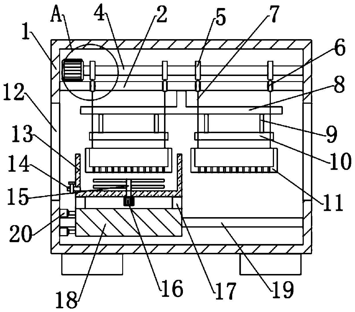
[0026] see Figure 1~3 , in an embodiment of the present invention, a dyeing processing device for socks includes a housing 1, the inside of the housing 1 is fixedly connected with a top plate 2, and the bottom of the top plate 2 is fixedly connected with a connecting plate 8, the A dyeing frame 11 is arranged on the lower side of the left and right ends of the connecting plate 8, and the dyeing frame 11 is connected with the driving mechanism arranged at the top of the top plate 2, and the dyeing box 13 is arranged on the lower side of the dyeing frame 11, and the bottom of the dyeing box 13 Connected with the moving mechanism, openings 12 are provided on the left and right sides of the casing 1 .

Embodiment 2

[0028] In this embodiment, the longitudinal section of the connecting plate 8 is a "T"-shaped structure.

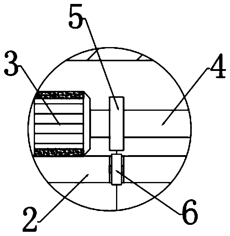
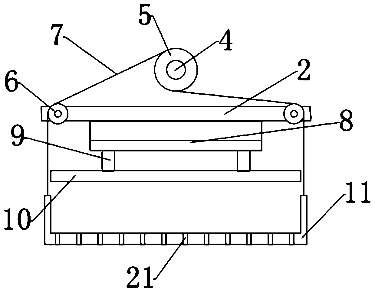
[0029] In this embodiment, the drive mechanism includes a first motor 3, a rotating rod 4, a runner 5 and a pull cord 7, and the first motor 3 is bolt-connected and arranged on the top of the top plate 2, and the output on the right side of the first motor 3 is The end is connected with the rotating rod 4, and the rotating rod 4 is fixedly connected with several runners 5, and the upper and lower sides of the runner 5 are fixedly connected with stay ropes 7, and the other ends of the stay ropes 7 on both sides are connected with the dyeing frame respectively. 11. The frame walls on both sides of the front and rear sides are fixedly connected. By setting the driving mechanism, the dyeing frames 11 on the left and right sides can be lifted and lowered at the same time, so that the dyeing frame 11 can fully contact with the dyeing box 13, and the dyeing frame 11 on one side c...


PUM


Abstract

The invention relates to the technical field of sock production, in particular to a dyeing processing device for socks. The device comprises a shell, a top plate is fixedly connected to the inner sideof the shell, a connecting plate is fixedly connected to the bottom of the top plate, dyeing frames are arranged on the lower sides of the left end and the right end of the connecting plate respectively, the dyeing frames are connected with a driving mechanism arranged on the top of the top plate, a dyeing box is arranged below one dyeing frame, the bottom of the dyeing box is connected with a moving mechanism. Accordingly, by arranging the driving mechanism, the dyeing frames on the left side and the right side can rise and fall at the same time, the dyeing frames can make full contact withthe dyeing box, and when the dyeing frame on one side performs dyeing, the dyeing frame on the other side performs feeding conveniently; by arranging pressing plates, socks located in the dyeing frames can be pressed in the process that the socks leave the dyeing box, so that residual dyeing liquid in the socks is discharged, and waste of the dyeing liquid is lowered; meanwhile, the dyed socks canbe dried rapidly, and subsequent processing is facilitated.

Description

technical field [0001] The invention relates to the technical field of socks production, in particular to a dyeing processing device for socks. Background technique [0002] With the development of society and the continuous advancement of science and technology, people's requirements for the living environment are higher and higher, and the requirements for basic necessities of life are also increasing. Among them, socks are necessary clothing for people's daily life, and the production of socks also needs to use There are a lot of equipment, among which the dyeing machine is a kind of bleaching and dyeing equipment for dyeing and processing finished socks. Now the market demand for socks is also increasing, so there are more and more processing equipment for socks. [0003] The existing equipment is to put the socks into the dyeing box, then stir them, and dye them with the dye liquid. After the dyeing is completed, the dye liquid in the equipment is discharged, and then t...

Claims


Application Information

Patent Timeline
Patent Type & Authority Applications(China)
IPC IPC(8): D06B3/30D06B15/00D06B23/04D06B23/20
CPCD06B3/30D06B23/04D06B15/005D06B23/20
Inventor 翁荣金刘爱莲张体健
Owner LANGSHA KNITTING
Why Eureka
Try Eureka