

An electrolytic cell sealing device and its manufacturing method
A sealing device and manufacturing method technology, applied in the direction of electrolysis components, electrolysis process, engine sealing, etc., can solve the problems of human body damage, life-threatening, hydrogen explosion, etc., and achieve the effect of easy operation, time saving and easy replacement
- Summary
- Abstract
- Description
- Claims
- Application Information
AI Technical Summary
Problems solved by technology
Method used
Image

Examples
Embodiment 1
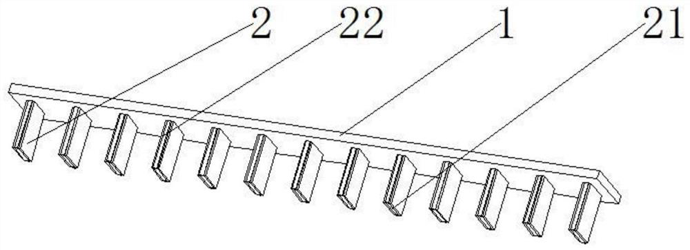
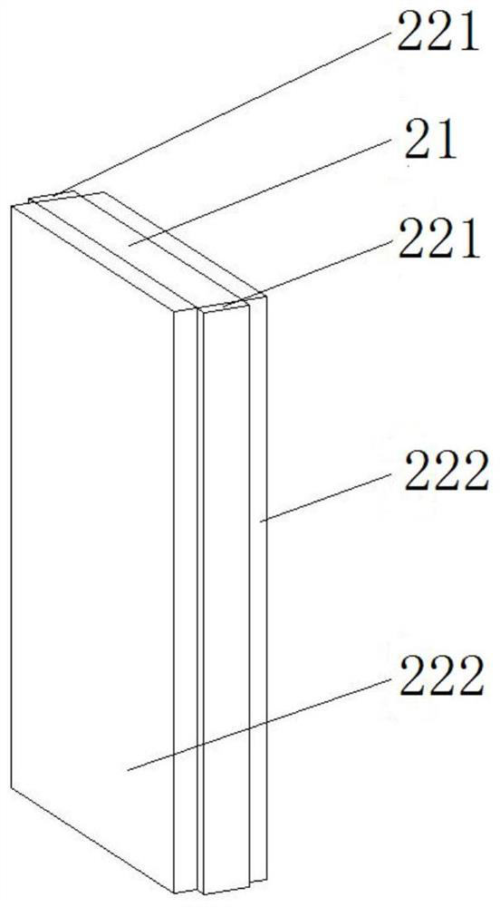
[0034] see figure 1 and 2 , figure 1 It is a structural schematic diagram of the electrolytic cell sealing device of the present invention; figure 2 for figure 1 Schematic diagram of the structure of one of the seals. As shown in the figure, the electrolytic cell sealing device includes a main body 1 and a plurality of seals 2, the seals 2 are arranged at intervals on the surface of the main body 1, the seals 2 include a sealing body 21 and a foam layer 22, and the foam layer 22 covers The body 21 is sealed.
[0035] In this embodiment, the foam layer 22 includes two first foam layers 221 and two second foam layers 222, and the sealing body 21 has two corresponding first surfaces and two corresponding second surfaces , the first surface is perpendicular to the length direction of the main body 1, and the second surface is parallel to the length direction of the main body 1; the two first foam layers 221 are respectively arranged on the two first surfaces, and the two sec...
Embodiment 2
[0044] see figure 1 and 2 , figure 1 It is a structural schematic diagram of the electrolytic cell sealing device of the present invention; figure 2 for figure 1 Schematic diagram of the structure of one of the seals. As shown in the figure, the electrolytic cell sealing device includes a main body 1 and a plurality of seals 2, the seals 2 are arranged at intervals on the surface of the main body 1, the seals 2 include a sealing body 21 and a foam layer 22, and the foam layer 22 covers The body 21 is sealed.
[0045] In this embodiment, the foam layer 22 includes two first foam layers 221 and two second foam layers 222, and the sealing body 21 has two corresponding first surfaces and two corresponding second surfaces , the first surface is perpendicular to the length direction of the main body 1, and the second surface is parallel to the length direction of the main body 1; the two first foam layers 221 are respectively arranged on the two first surfaces, and the two sec...
Embodiment 3
[0053] see figure 1 and 2 , figure 1 It is a structural schematic diagram of the electrolytic cell sealing device of the present invention; figure 2 for figure 1 Schematic diagram of the structure of one of the seals. As shown in the figure, the electrolytic cell sealing device includes a main body 1 and a plurality of seals 2, the seals 2 are arranged at intervals on the surface of the main body 1, the seals 2 include a sealing body 21 and a foam layer 22, and the foam layer 22 covers The body 21 is sealed.
[0054] In this embodiment, the foam layer 22 includes two first foam layers 221 and two second foam layers 222, and the sealing body 21 has two corresponding first surfaces and two corresponding second surfaces , the first surface is perpendicular to the length direction of the main body 1, and the second surface is parallel to the length direction of the main body 1; the two first foam layers 221 are respectively arranged on the two first surfaces, and the two sec...
PUM
 Abstract
Description
Claims
Application Information