Ditcher cutterhead with lubrication function

A ditching machine and cutter head technology, applied in the direction of excavation/covering trenches, planting methods, applications, etc., can solve the problems of affecting the speed of ditching, increasing investment costs, rusting at the joint of the cutter, etc., and achieves convenient disassembly , Improve the effect of ditching effect

Inactive Publication Date: 2019-12-03
SAYANG CASTLE AGRI MACHINERY CO LTD
View PDF0 Cites 1 Cited by
  • Summary
  • Abstract
  • Description
  • Claims
  • Application Information

AI Technical Summary

Problems solved by technology

There are various types of cutterheads for existing ditching machines, but usually the cutterheads have poor cutting performance and high power consumption. At the same time, the processing of parts is difficult and the cost is high, and the cutterheads are usually integrally poured and formed at one time. When the ditching machine ditches, the blades It is very easy to wear, and the existing overall cutter head cannot replace the local blades, which reduces the ditching efficiency of the trencher. If the cutter head is replaced frequently, the investment cost will increase. After the cutter is damaged, if it is not replaced in time, it will directly affect the ditching. ditch effect
At the same time, when the ditching machine is used for ditching for a long time, it is easy to reduce the lubrication of the cutter head, rust the joint of the cutter, and affect the speed of ditching

Method used


Image

  • Ditcher cutterhead with lubrication function
  • Ditcher cutterhead with lubrication function

Examples


Embodiment Construction

[0014] The following will clearly and completely describe the technical solutions in the embodiments of the present invention with reference to the accompanying drawings in the embodiments of the present invention. Obviously, the described embodiments are only some, not all, embodiments of the present invention. Based on the embodiments of the present invention, all other embodiments obtained by persons of ordinary skill in the art without making creative efforts belong to the protection scope of the present invention.

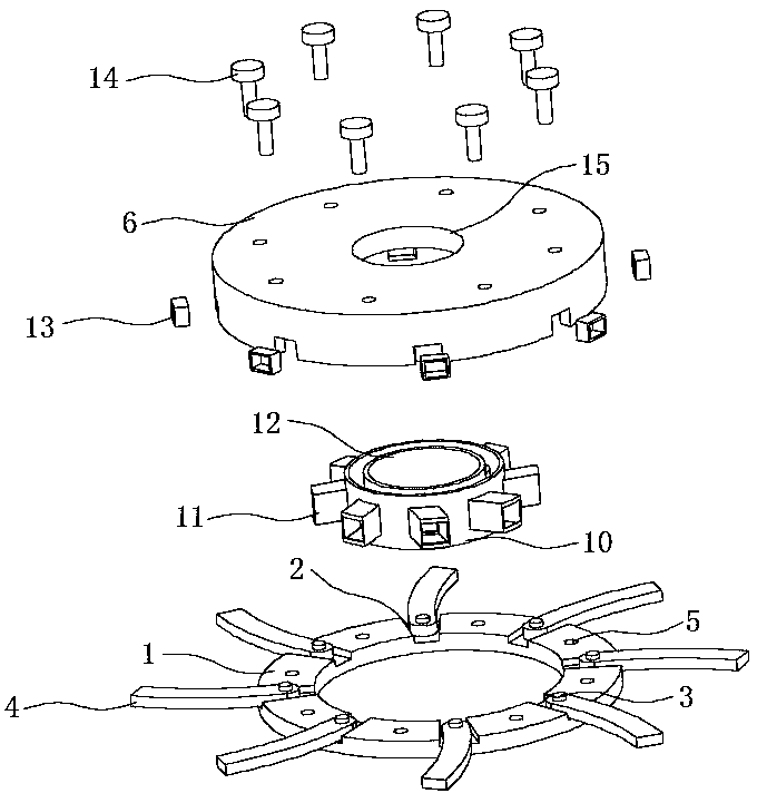
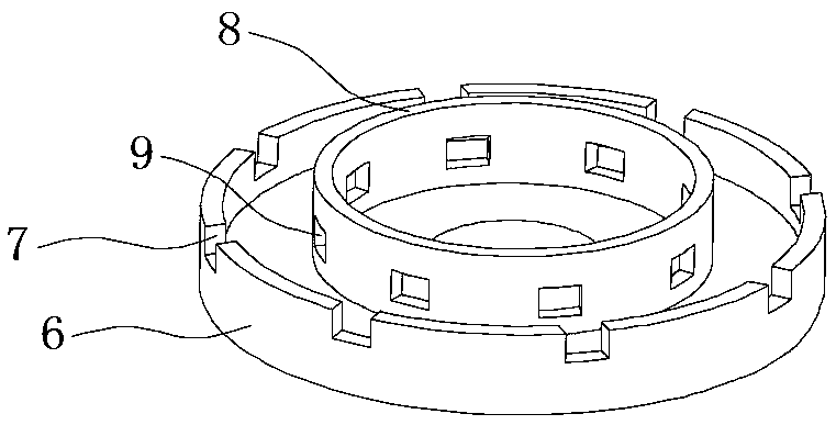
[0015] see Figure 1-2 , the present invention provides a technical solution: a ditching machine cutter head with lubricating function, including a cutter head seat 1, the upper end surface of the cutter head seat 1 is provided with a first clamping groove 2, and the first clamping groove 2 The middle part of the upper end in the groove is fixedly installed with a fixed pin shaft 3, the upper end of the fixed pin shaft 3 is movably socketed with a tool 4, and ...


PUM


Abstract

The invention discloses a ditcher cutterhead with a lubrication function. The ditcher cutterhead with the lubrication function comprises a cutterhead base, first clamping grooves are formed in the upper end surface of the cutterhead base, fixing pin rolls are fixedly installed in the middles of the upper ends in the first clamping grooves, and cutters movably sleeve the upper ends of the fixing pin rolls; the cutterhead base is connected with a cutterhead cover through a fixing bolt, second clamping grooves are formed in the outer side surface of the cutterhead cover, and a second hole grooveis formed in the middle of the upper end surface of the cutterhead cover; a boss is fixedly installed in the middle of the upper surface of an inner cavity of the cutterhead cover, third clamping grooves are formed in the middle of the outer side surface of the boss, and a lubricating oil tank is fixedly installed in the middle of the upper surface of the inner cavity of the cutterhead cover; oiloutlet pipes are fixedly installed on the outer side surface of the lubricating oil tank, and a first hole groove is formed in the middle of the upper end surface of the lubricating oil tank. The ditcher cutterhead with the lubrication function not only can timely check and replace the cutters, but also can lubricate joints of a cutterhead body and the cutters, and the ditching speed is increased.

Description

technical field [0001] The invention relates to the technical field of agricultural machinery, in particular to a ditching machine cutter head with a lubricating function. Background technique [0002] With the gradual popularization and application of agricultural machinery and automation, there have been many automated machinery for farming. Especially the application of agricultural ditching machines has brought great convenience to agricultural planting. The ditching machine is a new efficient and practical chain type ditching device. It is mainly composed of power system, deceleration system, chain transmission system and soil distribution system. After the diesel engine transmits the rotation to the clutch through the belt, it drives the travel gearbox, drive shaft, rear axle, etc. to realize the forward or backward linear motion of the chain trencher. There are various types of cutterheads for existing ditching machines, but usually the cutterheads have poor cuttin...

Claims


Application Information

Patent Timeline
Patent Type & Authority Applications(China)
IPC IPC(8): A01C5/06
CPCA01C5/064
Inventor 刘青山
Owner SAYANG CASTLE AGRI MACHINERY CO LTD
Why Eureka
Try Eureka