Timber cutting device

A cutting device and wood technology, applied in the direction of sawing equipment, wood processing equipment, circular saws, etc., can solve the problems of manual pressing, affecting cutting effect and work efficiency, easy to get stuck in wood, etc., to improve work efficiency and enhance cutting Effect, the effect of reducing labor intensity

Inactive Publication Date: 2019-12-03
任宇飞
View PDF0 Cites 4 Cited by
  • Summary
  • Abstract
  • Description
  • Claims
  • Application Information

AI Technical Summary

Problems solved by technology

In the existing technology, most of the cutting of wood is cut by electric saw, but most of the cutting of electric saw needs manual pressing, and the electric saw is easy to get stuck in the wood during the process of cutting wood, which affects the cutting effect and work efficiency

Method used


Image

  • Timber cutting device
  • Timber cutting device
  • Timber cutting device

Examples


Embodiment 1

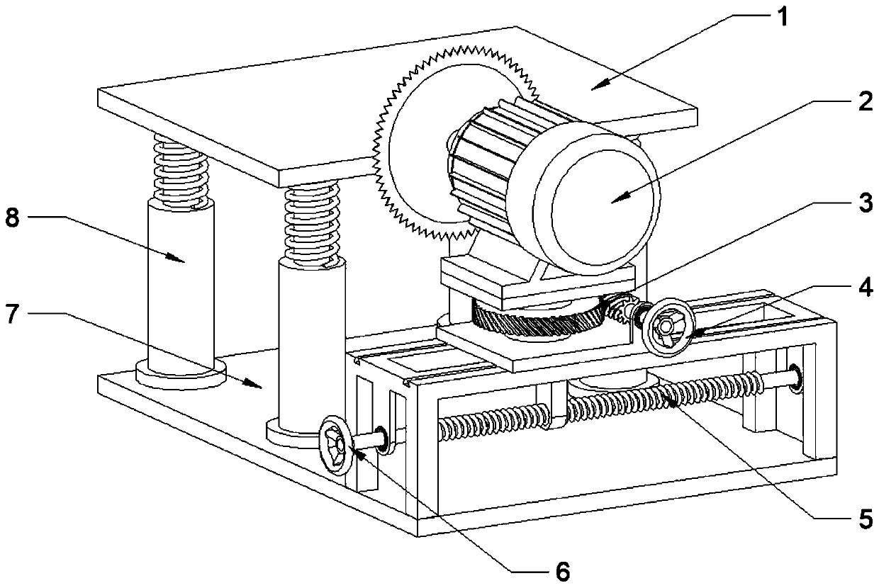
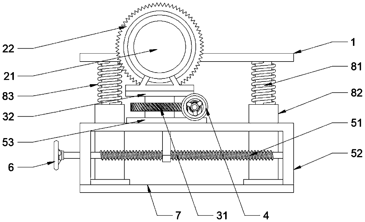
[0023] see Figure 1~3 , in an embodiment of the present invention, a wood cutting device includes a workbench 1 and a cutting assembly 2, the workbench 1 and the cutting assembly 2 are both arranged above the base 7, and the workbench 1 is installed on the base through a lifting assembly 8 On the base 7, one end of the lifting assembly 8 is arranged on the bottom of the workbench 1, and the other end is fixedly installed on the base 7, and the cutting assembly 2 is arranged on the base 7 through an adjusting device, and the adjusting device includes a rotating assembly 3 and a sliding assembly 5, the cutting assembly 2 is fixedly installed on the rotating assembly 3, the bottom of the rotating assembly 3 is connected to the sliding assembly 5 in rotation, and the sliding assembly 5 is fixedly installed on the base 7; the workbench 1 It is used to place and fix the wood, which is convenient for the cutting assembly 2 to cut. The rotating assembly 3 can drive the cutting assemb...

Embodiment 2

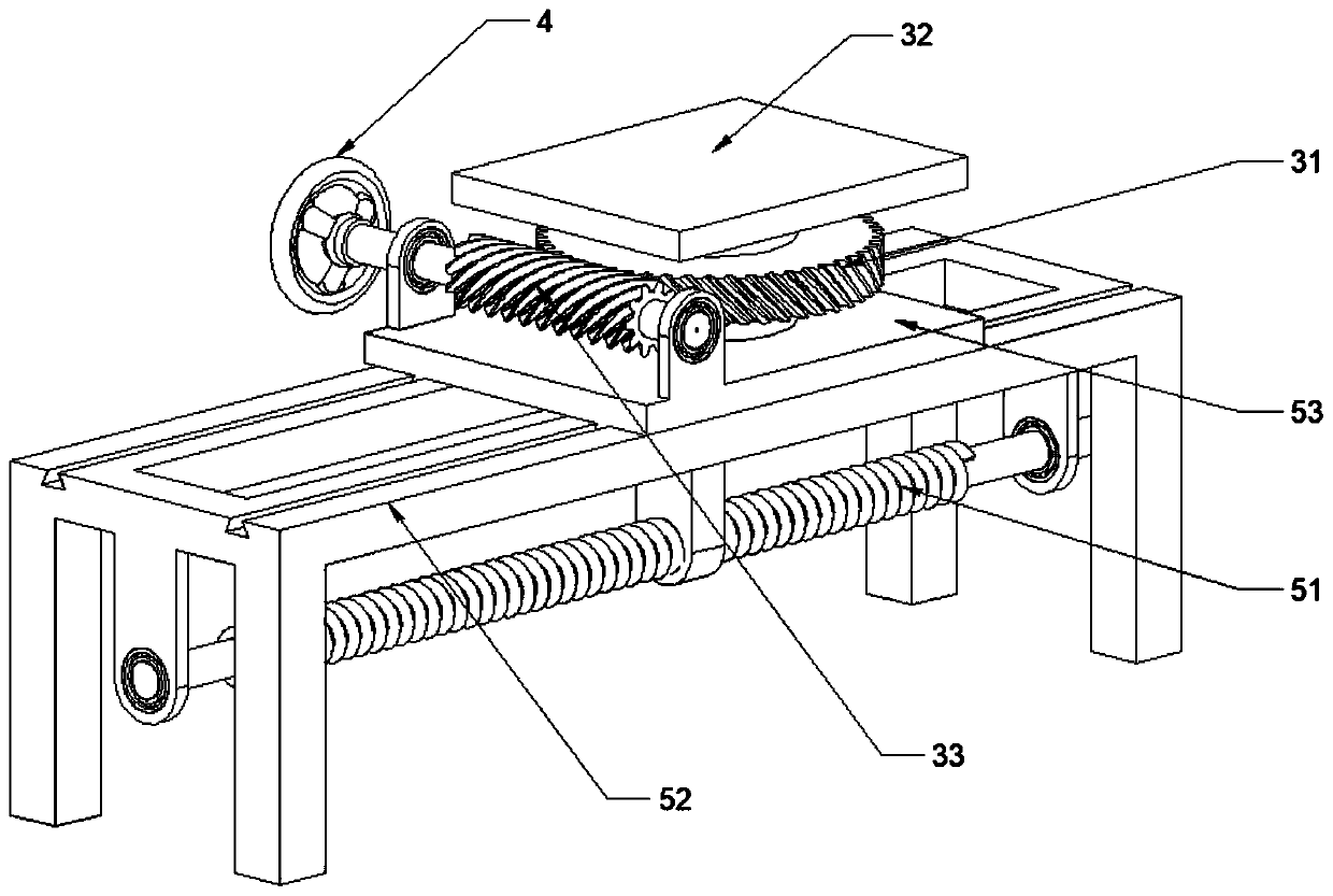
[0029] see Figure 4 , in the embodiment of the present invention, a wood cutting device, on the basis of embodiment 1, the rotating handle 4 and the sliding handle 6 are respectively replaced by a rotating motor 9 and a sliding motor 10, and the rotating motor 9 is fixedly installed on the sliding bottom plate 53, and set in linkage with the worm 33 through a coupling, the rotating motor 9 drives the worm 33 to rotate, and can adjust the cutting angle of the cutting assembly 2; the sliding motor 10 is fixedly installed on the base 7, and through the coupling The device is set in linkage with the adjusting screw 51, the sliding motor 10 drives the adjusting screw 51 to rotate, and the cutting width of the cutting assembly 2 can be adjusted; the angle, radian and width of wood cutting are precisely controlled by the rotating motor 9 and the sliding motor 10, and the cutting effect is enhanced , Change manual mode to automatic mode, reduce labor intensity and improve work effici...


PUM


Abstract

The invention discloses a timber cutting device. The device comprises a workbench and a cutting assembly, the workbench and the cutting assembly are both arranged above the base. The workbench is installed on the base through a lifting assembly. One end of the lifting assembly is arranged at the bottom of the workbench. One end of the cutting assembly is fixedly installed on the base, the other end of the cutting assembly is fixedly installed on the base, the cutting assembly is arranged on the base through an adjusting device, the adjusting device comprises a rotating assembly and a sliding assembly, the cutting assembly is fixedly installed on the rotating assembly, the lower portion of the rotating assembly is rotationally connected with the sliding assembly, and the sliding assembly isfixedly installed on the base. The rotating assembly and the sliding assembly are adopted, the angle, radian and width of timber cut by the electric saw blade are adjusted, timber cutting with special cutting requirements is met, and the application range is wide; and the lifting assembly is adopted, wood chips at the cutting position can be shaken off in time, the situation that the cutting effect is affected by wood chip accumulation is avoided, meanwhile, the cutting assembly is prevented from being clamped by wood, and working efficiency is improved.

Description

technical field [0001] The invention relates to the technical field of wood processing equipment, in particular to a wood cutting device. Background technique [0002] Wood is a widely used material in people's lives, and wood cutting is the most common process in wood processing. In the existing technology, most of the cutting of wood is cut by electric saw, but most of the cutting of electric saw requires manual pressing, and the electric saw is easy to get stuck in the wood during the process of cutting wood, which affects the cutting effect and work efficiency. Contents of the invention [0003] The purpose of the present invention is to provide a wood cutting device to solve the problems raised in the above-mentioned background technology. [0004] To achieve the above object, the present invention provides the following technical solutions: [0005] A wood cutting device, comprising a workbench and a cutting assembly, the workbench and the cutting assembly are both...

Claims


Application Information

Patent Timeline
Patent Type & Authority Applications(China)
IPC IPC(8): B27B5/06B27B5/29B27G3/00B27B5/20B27B5/16B27G19/02
CPCB27B5/06B27B5/16B27B5/20B27B5/29B27G3/00B27G19/02
Inventor 任宇飞
Owner 任宇飞
Why Eureka
Try Eureka