
Die for forming concrete pipe pile

A technology of concrete pipe piles and molds, which is applied in the direction of molds, etc., can solve the problem of limited increase in relative friction between the pile body and the surrounding soil, loose fit between arc blocks and the outer wall of the small diameter section, and complex structure of concave-convex prefabricated pile molds and other problems, to achieve the effect of preventing mold deformation, simple structure, and enhancing pull-out bearing performance

Pending Publication Date: 2019-12-03
周兆弟
View PDF7 Cites 1 Cited by
  • Summary
  • Abstract
  • Description
  • Claims
  • Application Information

AI Technical Summary

Problems solved by technology

[0005] Although the above-mentioned concave-convex prefabricated pile mold can be used to make variable-section piles that improve the uplift bearing performance through the concave-convex molded plate, there is a problem of complex structure in the concave-convex precast pile mold; The inner wall of the mold and the lower mold fits together, which makes the outer end surface of the prefabricated reinforcement of the formed prefabricated pile flush with the outer wall surface of the large diameter section of the prefabricated pile. Then, when the prefabricated pile is used, the prefabricated reinforcement separates the surrounding soil into multiple parts. Isolated arc-shaped block, which makes the arc-shaped block and the outer wall of the small-diameter section not tightly fitted, resulting in a limited increase in the relative friction between the pile body and the surrounding soil, thereby improving the uplift bearing performance of the concave-convex prefabricated pile limited

Method used


Image

  • Die for forming concrete pipe pile
  • Die for forming concrete pipe pile
  • Die for forming concrete pipe pile

Examples


Embodiment 1

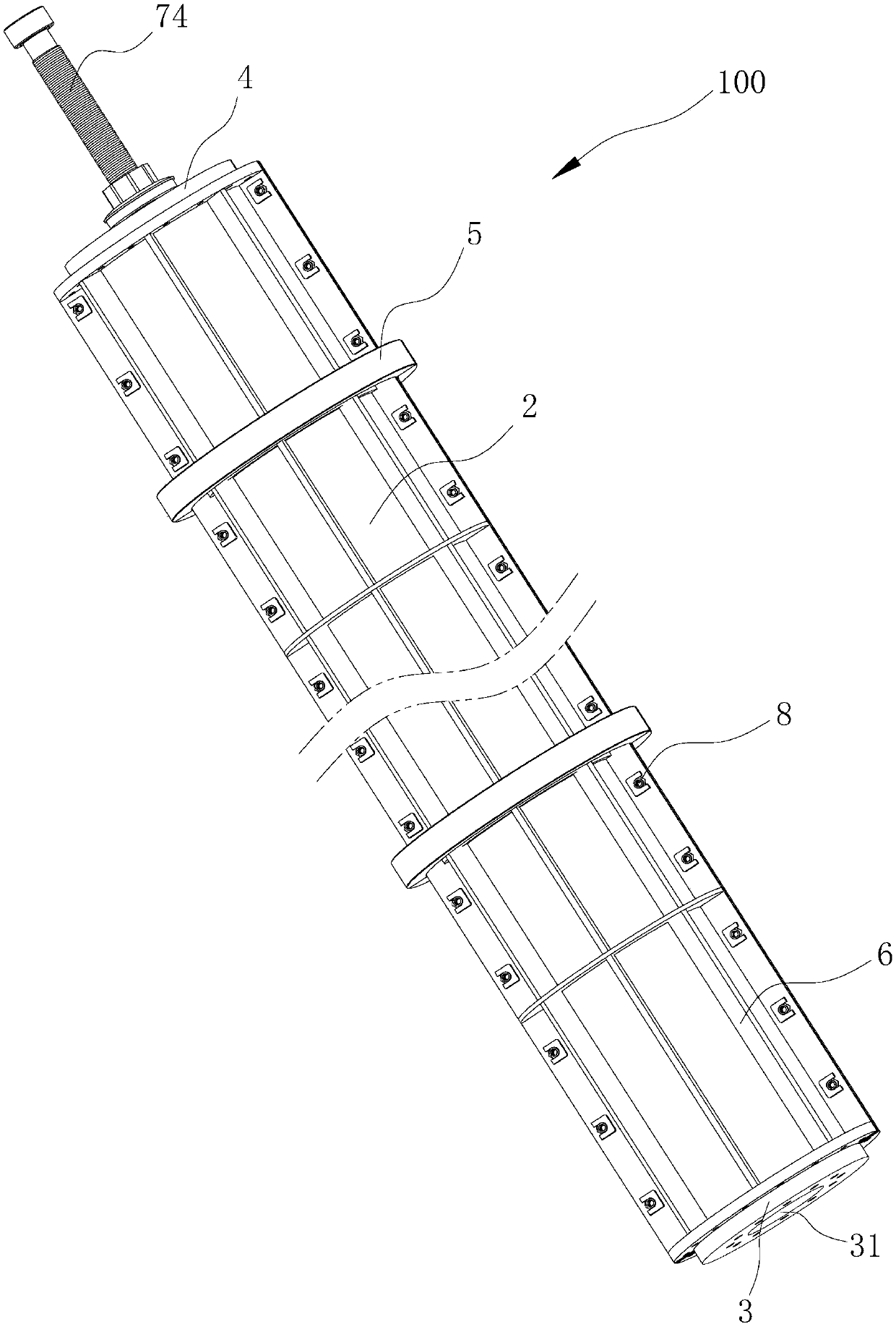
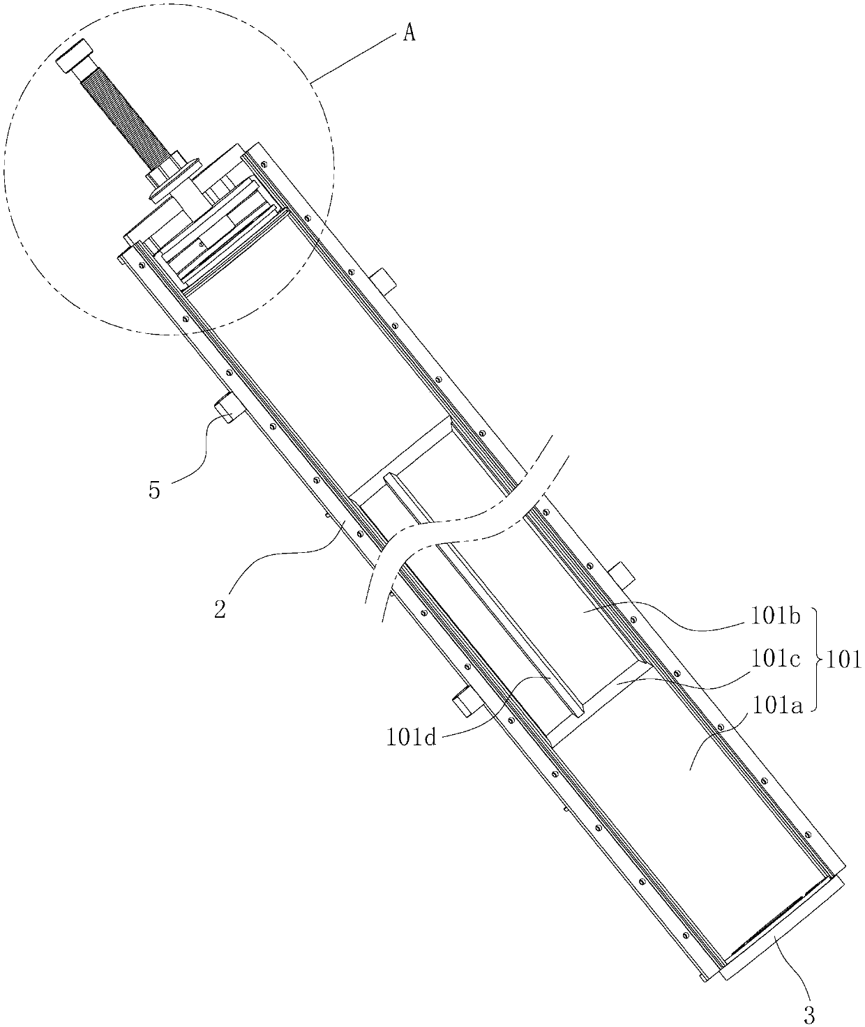
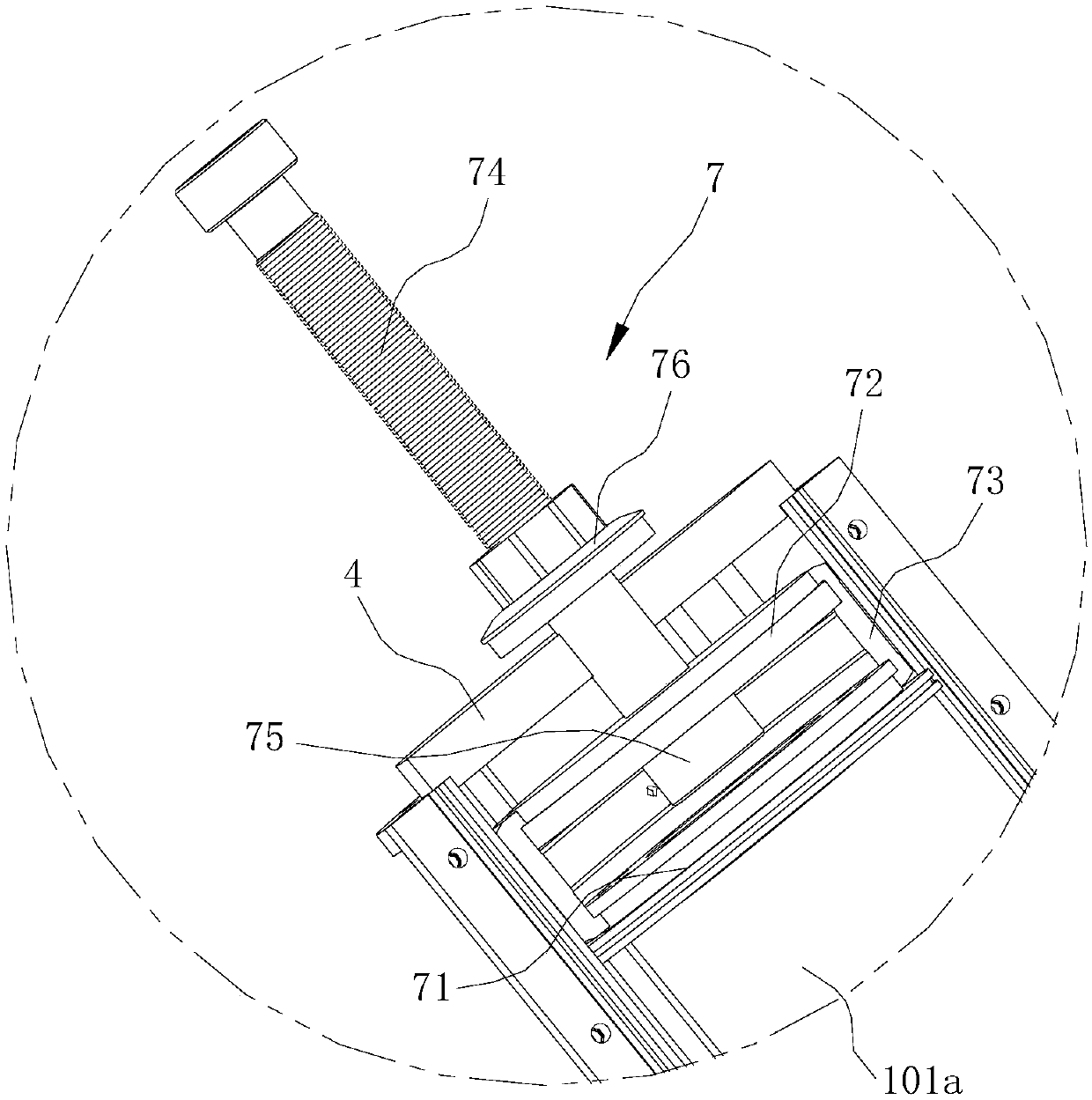
[0079] like figure 1 and figure 2 As shown, the present embodiment provides a mold 100 for forming concrete pipe piles, the mold cavity 101 of the mold 100 forms a plurality of thick pile hole sections 101a and a plurality of thin pile hole sections 101b along the length direction, each thick pile hole The sections 101a and the thin pile hole sections 101b are alternately arranged and communicated with each other. Of course, in the mold 100 provided by the present invention, at least one thick pile hole section 101 a and one thin pile hole section 101 b are formed along the length direction of the mold cavity 101 of the mold 100 .

[0080] like figure 2 and Figure 5 As shown, the hole wall of the thin pile hole section 101b is circularly uniformly distributed with four grooves 101d around the central axis. The lengthwise direction of the groove 101d coincides with the lengthwise direction of the mold 100 . Certainly, in the mold 100 provided by the present invention, a...

Embodiment 2

[0096] In this embodiment, the parts that are the same as in the first embodiment are given the same reference numerals, and the same text descriptions are omitted.

[0097] like Figure 8 to Figure 9 As shown, compared with Embodiment 1, the mold 100 for forming concrete pipe piles provided by this embodiment also has such a structure:

[0098]The hole wall of the thick pile hole section 101a is provided with four ribs 101e at equal intervals around the central axis, wherein the length direction of the ribs 101e is consistent with the length direction of the mold 100, and in the radial direction of the mold 100, the ribs 101e The convex height H2 is less than the difference between the inner hole radius R1 of the thick pile hole section 101a and the inner hole radius R2 of the thin pile hole section 101b.

[0099] like Figure 9 As shown, in this embodiment, in order to facilitate demoulding, the two side walls of the rib 101e are provided with a draft angle α2 of 1° to 75°...

Embodiment 3

[0106] In this embodiment, the parts that are the same as in the first embodiment are given the same reference numerals, and the same text descriptions are omitted.

[0107] like Figure 11 As shown, compared with Embodiment 1, the mold 100 for forming concrete pipe piles provided by this embodiment also has such a structure: in the length direction of the mold 100 from the first end plate 3 to the second end plate 4 or by In the length direction of the mold 100 from the second end plate 4 to the first end plate 3, the inner diameters of the thick pile hole sections 101a increase sequentially, and the inner diameters of the thin pile hole sections 101b increase sequentially.

[0108] Of course, in the mold 100 provided by the present invention, it can also be in the length direction of the mold 100 from the first end plate 3 to the second end plate 4 or the length of the mold 100 from the second end plate 4 to the first end plate 3 direction, only the inner diameter of each t...


PUM


Abstract

The invention discloses a die for forming a concrete pipe pile, which is characterized in that a die cavity of the die is equipped with at least one thick pile hole section and at least one thin pilehole section along a length direction, and the thick pile hole section is communicated with the thin pile hole section, wherein at least one groove is formed in the hole wall of the thin pile hole section, the length direction of the groove is consistent with the length direction of the die, the difference between the radius value of an inner hole of the thick pile hole section and the radius value of an inner hole of the thin pile hole section is larger than the groove depth of the groove, and a shaft shoulder surface is formed between the hole wall of the thick pile hole section and the holewall of the adjacent thin pile hole section. The die for forming the concrete pipe pile has the advantage of being simple in structure, the concrete pipe pile with better anti-pulling bearing performance can be conveniently manufactured and formed, but also the overall structural strength of the die is greatly improved, and the die is prevented from deforming.

Description

technical field [0001] The invention relates to the field of pipe piles, in particular to a mold for forming concrete pipe piles. Background technique [0002] Under normal circumstances, reinforced concrete prefabricated piles are prefabricated in factories using molds, and then transported to the location where the piles are located. On the basis of a certain degree of application of hammering, static pressure and other technological measures, the The pile body enters the predetermined position. Compared with other piles, the reinforced concrete prefabricated pile shows a relatively strong load capacity, relatively small settlement deformation, simple construction, low cost and relatively high efficiency in the process of practical application. High advantages, so it has been widely used in pile foundation engineering. [0003] Chinese Utility Model Patent (CN 206796169U) discloses a concave-convex prefabricated pile mould. The concave-convex prefabricated pile mold inclu...

Claims


Application Information

Patent Timeline
Patent Type & Authority Applications(China)
IPC IPC(8): B28B21/82
CPCB28B21/82
Inventor 周兆弟
Owner 周兆弟
Learn More