Off-orbit sail deployment method and device
A technology of de-orbiting and unfolding process, which is applied in the field of spacecraft de-orbiting, can solve problems such as the internal complexity of stars, and achieve the effects of preventing sudden damage, saving space, and ensuring support capacity
- Summary
- Abstract
- Description
- Claims
- Application Information
AI Technical Summary
Problems solved by technology
Method used
Image
Examples
Embodiment 1
[0046] This embodiment discloses an off-track sail deployment device.
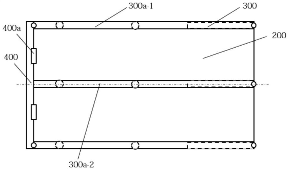
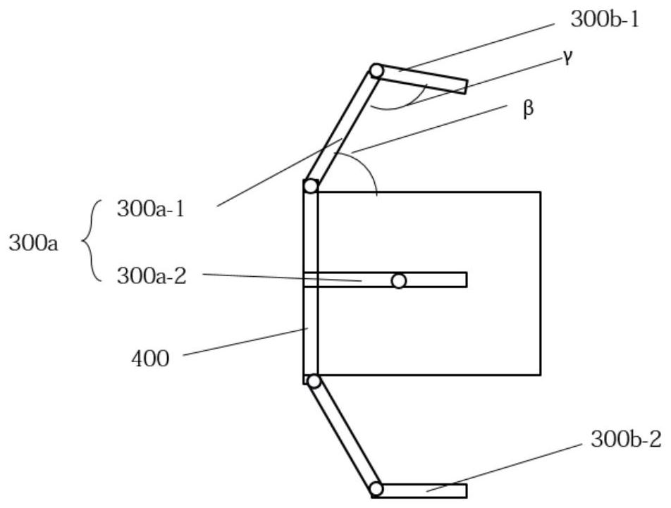
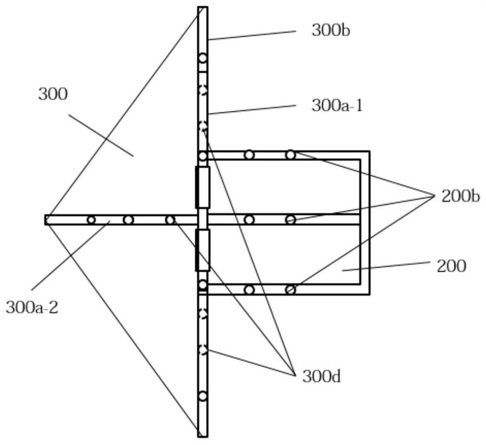
[0047] Such as Figure 1-5 As shown, the off-track sail deployment device includes a non-folding sail 200 and a folding sail 300 . The non-folding sail 200 is rotatably connected with the folding sail 300 to form a deorbiting sail for driving the star 100 out of orbit. Preferably, the first side of the unfolded sail 200 is provided with a connecting plate 400 . The connecting plate 400 is provided with a hinge 400a capable of turning the folding sail 300 relative to the first side.
[0048] The folding sail 300 includes at least one first frame 300a capable of folding the sail body in a folded state and supporting the sail body in an unfolded state. Preferably, the first skeleton 300a is light alloy steel, for example, material. The use of lightweight alloy steel can reduce the weight of the folding sail 300 on the premise that the mechanical construction rigidity and strength meet the technical specif...
Embodiment 2
[0060] This embodiment can be further improved and / or supplemented to the folding sail 300 in Embodiment 1, and the repeated content will not be repeated. In the case of no conflict or contradiction, the whole and / or part of the content of the preferred implementations of other embodiments may serve as supplements to this embodiment.
[0061] This embodiment discloses a preferred folding sail 300 that can at least be used in the off-track sail deployment device of Embodiment 1. The folding sail includes at least one first frame 300a and a sail body. Preferably, it may also include a second skeleton 300b. The sail body can be an aluminum membrane sail. It can be sewn on each skeleton with cotton thread. The sail body can be an independent sail body, or a plurality of sail bodies assembled between two first frames 300a. When the folding sail 300 is folded, the sail body can be in a folded state based on the first frame 300a and the second frame 300b. When the folding sail 3...
Embodiment 3
[0067] This embodiment may be a further improvement and / or supplement to Embodiment 1, and repeated content will not be repeated here. In the case of no conflict or contradiction, the whole and / or part of the content of the preferred implementations of other embodiments may serve as supplements to this embodiment.
[0068] Such as Figure 1-5 As shown, the off-track sail deployment device includes a non-folding sail 200 and a folding sail 300 . The non-folding sail 200 and the folding sail 300 are connected by a connecting plate 400 . A hinge 400a is disposed on the connecting plate 400 . Used to rotate the folding sail 300 around the non-folding sail 200 . The non-folding sail 200 is provided with a fixing mechanism at the opposite end of the connecting plate 400 . For example, the fixing mechanism includes a connecting wire and a fuse resistor. One end of the connection line and the fuse resistor are in a fixed state before receiving the off-track command. The other en...
PUM
 Abstract
Description
Claims
Application Information
 - R&D
- Intellectual Property
- Life Sciences
- Materials
- Tech Scout
- Unparalleled Data Quality
- Higher Quality Content
- 60% Fewer Hallucinations
Browse by: Latest US Patents, China's latest patents, Technical Efficacy Thesaurus, Application Domain, Technology Topic, Popular Technical Reports.
© 2025 PatSnap. All rights reserved.Legal|Privacy policy|Modern Slavery Act Transparency Statement|Sitemap|About US| Contact US: help@patsnap.com


