A treatment device for oil slick polluted waters

A treatment device and water area technology, applied in general water supply conservation, cleaning of open water surfaces, water conservancy projects, etc., can solve the problems of wide spread of oil pollution, high difficulty, low treatment efficiency, etc., and achieve simple operation, simple structure, and fast Efficient cleaning effect

Active Publication Date: 2020-10-27
永康市能泽科技有限公司
View PDF4 Cites 0 Cited by
  • Summary
  • Abstract
  • Description
  • Claims
  • Application Information

AI Technical Summary

Problems solved by technology

[0004] The existing treatment method is to deal with by adsorption method, the treatment efficiency is low, and because the oil pollution spreads widely, it is difficult to deal with it

Method used


Image

  • A treatment device for oil slick polluted waters
  • A treatment device for oil slick polluted waters
  • A treatment device for oil slick polluted waters

Examples


Embodiment 1

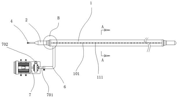
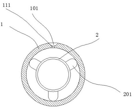
[0035] refer to figure 1 , figure 2 , image 3 and Figure 4The shown oil slick polluted waters treatment device includes an outer pipe 1 made of rubber, the thickness of the outer pipe is 3mm, the outer pipe is mainly responsible for contacting oil pollution, and the inner pipe 2 sleeved on the inner side of the outer pipe 1 , the thickness of the inner pipe is 0.85mm. The main function of the inner pipe is to be responsible for inflation and provide buoyancy. There are a plurality of raised parts 201 formed by injection molding at the center. The raised part is mainly to separate the inner pipe and the outer pipe. When the inner pipe is inflated, if no raised part is provided, the inner pipe may be inflated with the outer pipe. Form a contact seal between the outer pipes and inner pipes, which will affect the circulation of oil pollution between the outer pipe and the inner pipe. Therefore, we designed the raised part to ensure that there is a gap between the outer pipe ...

Embodiment 2

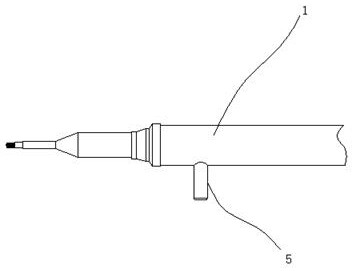
[0037] refer to Figure 5 and Figure 6 As shown, the outer wall of the outer pipe 1 is sheathed with a plurality of retaining sleeves 8, and the transition fit between the retaining sleeves 8 and the outer pipe 1, when the inner pipe 2 is inflated, the outer The outer diameter of the pipe 1 is expanded, and the expanded outer pipe 1 is in interference fit with the retaining sleeve 8 .

[0038] A stud 801 is welded at the outer wall of the retaining sleeve 8, and a counterweight ball 802 is fitted through the stud 801; the counterweight ball is mainly used for counterweighting, and the purpose of its design is that the density of salt water and fresh water is different. The same, the buoyancy produced is also different, so the reasonable floating height of the outer pipe can be maintained by the ball balance.

[0039] The weight ball 802 is a solid shot or steel ball.

Embodiment 3

[0041] refer to Figure 7 As shown, a locking piece 9 is arranged in the suction tube 5, the locking piece is U-shaped, the two ends of the locking piece 9 are expanded outwards, and both ends of the locking piece 9 are bent outwards. The claw part 901 is formed, and the locking member is made of spring steel. When assembling the liquid suction tube, firstly, a socket through the liquid suction tube is opened on the outer wall of the outer pipe, and the liquid suction tube is inserted into the socket , and then insert the locking piece, the locking piece slides in along the inner wall of the suction tube, and opens when the claw moves to the outside of the suction tube, at this time the claw is locked on the inner side of the outer tube The setting of the locking piece is mainly to limit the insertion depth of the suction pipe. When the insertion depth of the suction pipe is too large, it will contact with the inner pipe. After contact, the suction pipe will be located at the ...


PUM


Abstract

The invention discloses a floating oil contaminated water area processing device. The floating oil contaminated water area processing device comprises an outer pipeline and an inner pipeline, whereinthe outer pipeline is made of rubber, is 2-3 mm thick and is mainly used for making contact with oil contamination; the inner pipeline line is arranged on the inner side of the outer pipeline in a sleeving mode, is 0.85-1.25 mm thick, and is mainly used for inflation expanding so that buoyancy force can be provided; thus, the wall thickness does not need to be too large, and inflation expanding ofthe inner pipeline can be influenced by the too-large wall thickness; and the outer wall of the inner pipeline is provided with a plurality of convex strip parts through injection molding, and the convex strip parts are mainly used for insulating the inner pipeline from the outer pipeline. Through the floating oil contaminated water area processing device, gathering and collecting of the oil contamination can be achieved.

Description

technical field [0001] The invention relates to a treatment device for floating oil polluted waters. Background technique [0002] Ship transportation is a mode of transportation that uses ships to transport passengers or goods by water, and can be divided into coastal transportation and ocean transportation. Usually, the sea transportation between domestic coastal ports is called coastal transportation, and the sea transportation between domestic ports and foreign ports or between foreign ports and foreign ports is called ocean transportation. [0003] During transportation, we often find that there are oil spills, especially for some oil transport vessels. When leakage occurs, it will cause large-scale water surface pollution. [0004] The existing treatment method is to deal with by adsorption method, the treatment efficiency is low, and because the oil pollution spreads widely, it is difficult to deal with it. [0005] Based on the above problems, we designed a treatme...

Claims


Application Information

Patent Timeline
Patent Type & Authority Patents(China)
IPC IPC(8): E02B15/10
CPCE02B15/10Y02A20/204
Inventor 张伟彬杨文浪王达
Owner 永康市能泽科技有限公司
Why Eureka
Try Eureka