High and watery coastal area underground continuous wall connector water stop device

A water-stop device and water-rich technology, which is applied to sheet pile walls, water conservancy projects, underwater structures, etc., can solve the problems of the quality of underground diaphragm wall trenches, high construction costs of water-stop methods, and poor engineering geological conditions, etc. Problems, to achieve good wall brushing effect, ideal waterproof effect, and strengthen the overall effect

Pending Publication Date: 2019-12-03
QINGDAO TECHNOLOGICAL UNIVERSITY
View PDF2 Cites 7 Cited by
  • Summary
  • Abstract
  • Description
  • Claims
  • Application Information

AI Technical Summary

Problems solved by technology

In recent years, grouting joints have appeared. For example, 201810132066.4 discloses a groutable underground diaphragm wall joint and its construction method. The underground diaphragm wall joint, when the ground wall joint is connected by a rigid joint, the two grouting pipes are fixed on the side of the rigid joint facing the soil by a ring, and when the flexible joint is used, the two grouting pipes are respectively fixed on The two ends of the steel cage facing the soil surface, the specific construction includes: the construction of the guide wall, the unit groove section and the underground diaphragm wall; however, due to the poor engineering geological conditions, the quality of the groove formed by the underground diaphragm wall is a major and difficult point, and the construction cost of this water-stopping method is high

Method used


Image

  • High and watery coastal area underground continuous wall connector water stop device
  • High and watery coastal area underground continuous wall connector water stop device
  • High and watery coastal area underground continuous wall connector water stop device

Examples


Embodiment 1

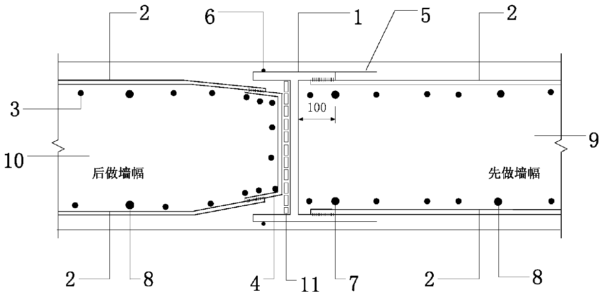
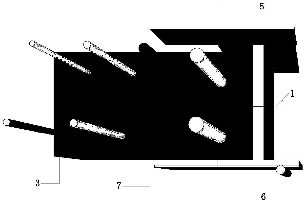
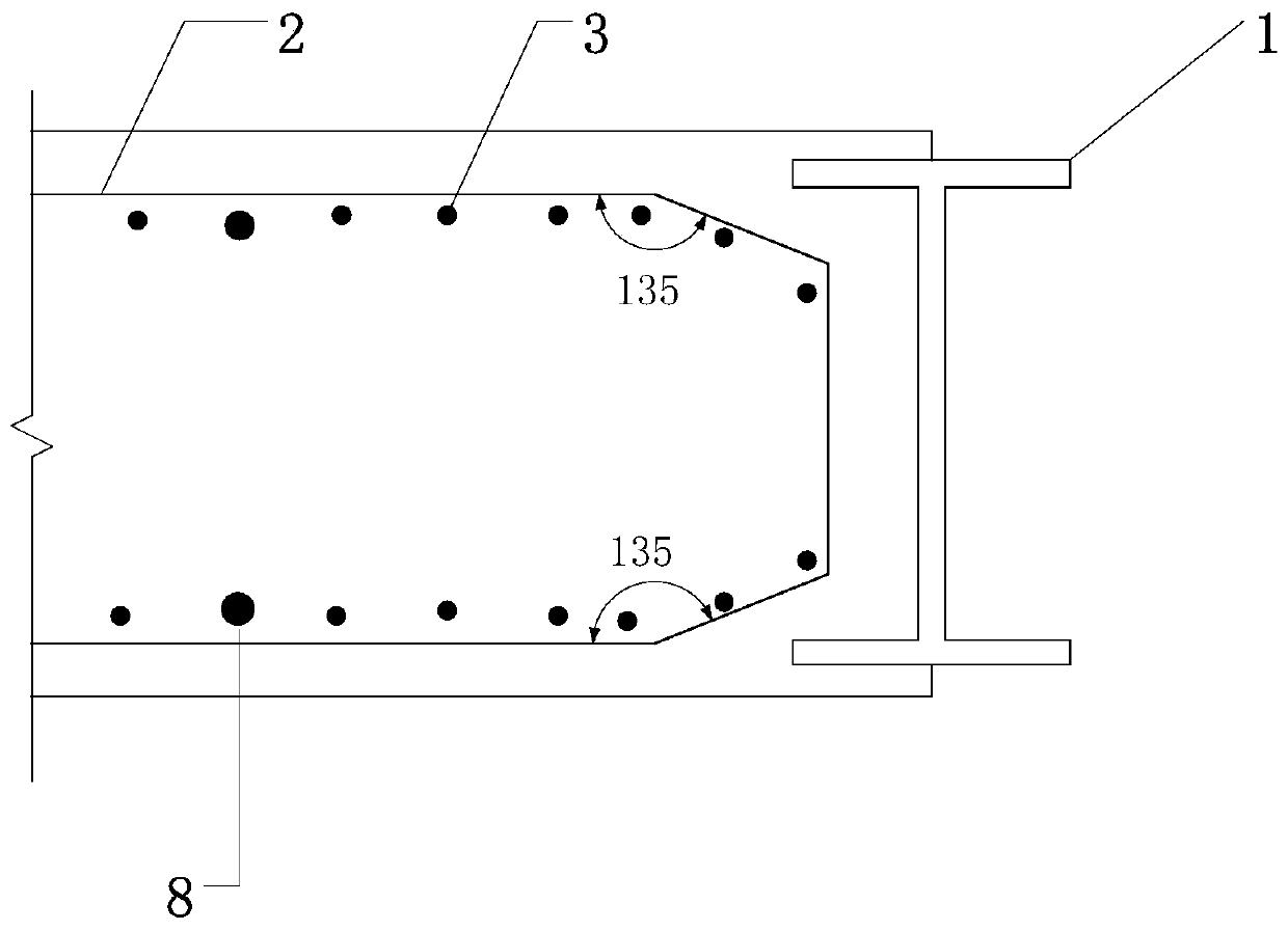
[0029] The main structure of the underground diaphragm wall joint water-stop device in the high-rich water near the sea area of ​​this embodiment includes I-shaped steel plate 1, diaphragm wall horizontal rib 2, diaphragm wall vertical main rib 3, U-shaped stirrup 4, galvanized iron sheet 5, layering strip Steel bar 6, steel flower pipe 7, grouting pipe 8, first wall reinforcement cage 9, second wall reinforcement cage 10 and sandbag 11; diaphragm wall horizontal reinforcement 2 and diaphragm wall vertical main reinforcement 3 are mechanically connected, and steel flower pipe 7 is bound Lap on the first wall reinforcement cage 9; the galvanized iron sheet 5 is installed on the outside of the I-shaped steel plate 1, the galvanized iron sheet 5 and the bead reinforcement 6 are spot welded, and the I-shaped steel 1 is welded to the first wall reinforcement cage 9 , the weld length is 100mm; the U-shaped stirrup 4 and the horizontal bar 2 of the continuous wall are welded on one si...

Embodiment 2

[0037] In this embodiment, the joint water-stop device described in Embodiment 1 is applied to the construction of an underground diaphragm wall of a certain subway station. The specific construction process is as follows:

[0038] (1) Pouring guide wall: After the measurement and setting-out is completed, the construction of the guide wall begins. The construction quality of the guide wall is directly related to the construction quality of the underground diaphragm wall. The cross-section of the guide wall is made of inverted "L" cast-in-place reinforced concrete, with HRB400C12@200 steel skeleton evenly distributed, and the guide wall is made of C30 concrete. Before excavation of the guide wall, the excavation trench must be manually excavated. When the excavator is operating, a special person must stand by Supervise the construction, then bind the guide wall reinforcement and vertical formwork, pour C30 concrete, remove the formwork and add lateral support, and finally backf...


PUM


Abstract

The invention belongs to the technical field of foundation pit supporting and relates to a high and watery coastal area underground continuous wall connector water stop device. Continuous wall horizontal ribs are mechanically connected with continuous wall vertical main beams. Steel flower pipes are bond to a first wall reinforcement cage in a lap joint manner. Galvanized sheet iron is installed on the outer side of an I-shaped steel plate. The galvanized sheet iron is welded to pressing bar steel bars in a spot welding manner. The I-shaped steel is connected with the first wall reinforcementcage in a welded manner. A U-shaped stirrup is connected with the single faces of the continuous wall horizontal ribs in a welded manner. Grouting pipes are bond to a second wall reinforcement cage ina lap joint manner. The second wall reinforcement cage is embedded and fixed in an I-shaped steel plate wing plate in a lifting manner. Sand bags are stacked on the outer side of an I-shaped steel plate connector web, and the lower filling height of the sand bags is the height of an underground continuous wall. The high and watery coastal area underground continuous wall connector water stop device is ideal in waterproof effect, concrete can be effectively prevented from streaming around, and due to the arrangement of the steel flower pipes, the water stop effect at the seam position is ensured.

Description

Technical field: [0001] The invention belongs to the technical field of foundation pit support, and relates to a water-stopping device for joints of continuous walls in high-water-rich coastal areas, in particular to a water-stopping device with I-shaped steel as the joint. Background technique: [0002] Diaphragm wall is an important form of deep foundation pit support structure. Its basic process includes: guide wall construction, mud preparation, trench construction, steel cage production, steel cage hoisting, joint treatment, underwater concrete pouring, etc. , wherein the construction of the joints of the underground diaphragm wall (especially in a high-rich water-facing area) is a technical problem affecting the anti-seepage and water-proofing of the underground diaphragm wall. [0003] At present, the commonly used construction methods at the joints of underground diaphragm walls include the following: One is the circular joint pipe technology: after cleaning the bott...

Claims


Application Information

Patent Timeline
Patent Type & Authority Applications(China)
IPC IPC(8): E02D5/18E02D29/16
CPCE02D5/187E02D29/16E02D2250/0023
Inventor 白晓宇张明义王永洪王海刚
Owner QINGDAO TECHNOLOGICAL UNIVERSITY
Why Eureka
Try Eureka