Air filter air outlet pipe

A technology of air outlet pipe and air filter, which is applied in the direction of combustion air/combustion-air treatment, mechanical equipment, engine components, etc., and can solve problems such as difficult safety clearance between pipelines and surrounding parts, unfavorable lightweight design, and difficult shape control

Pending Publication Date: 2019-12-03
SAIC-GM-WULING AUTOMOBILE CO LTD
View PDF7 Cites 0 Cited by
  • Summary
  • Abstract
  • Description
  • Claims
  • Application Information

AI Technical Summary

Problems solved by technology

[0003] At present, the air filter exhaust pipe assembly (such as figure 1 and as figure 2 As shown), it mainly includes the air filter outlet pipe 01, the pressure relief pipe joint 02, the PCV pipe joint 03 and the clamp 04 installed at both ends of the air filter outlet pipe 01. This air filter outlet pipe assembly has some shortcomings: (1) The AEM or FKM rubber tube is an elastic body, the shape is not easy to control, and the manufacturing error is relatively large; when the boundary space around the AEM or FKM is relatively small, it is difficult to ensure the safety clearance between the pipeline and the surrounding parts, and interference wear is likely to occur; (2) Due to the vibration isolation of the air filter outlet pipe, the pipeline design is generally relatively long, and the materials of AEM and FKM are very expensive, and the long pipeline will require a lot of materials, so the parts cost of the air filter outlet pipe is very high; ( 3) The entire section of the air filter outlet pipe is made of rubber material. In order to meet the requirements of negative pressure resistance, the wall thickness of the pipe needs to be designed thicker; or a lot of reinforcement ribs are designed to prevent collapse, which will inevitably lead to an increase in the weight of the parts, which is not conducive to lightweight design

Method used


Image

  • Air filter air outlet pipe
  • Air filter air outlet pipe
  • Air filter air outlet pipe

Examples


Embodiment Construction

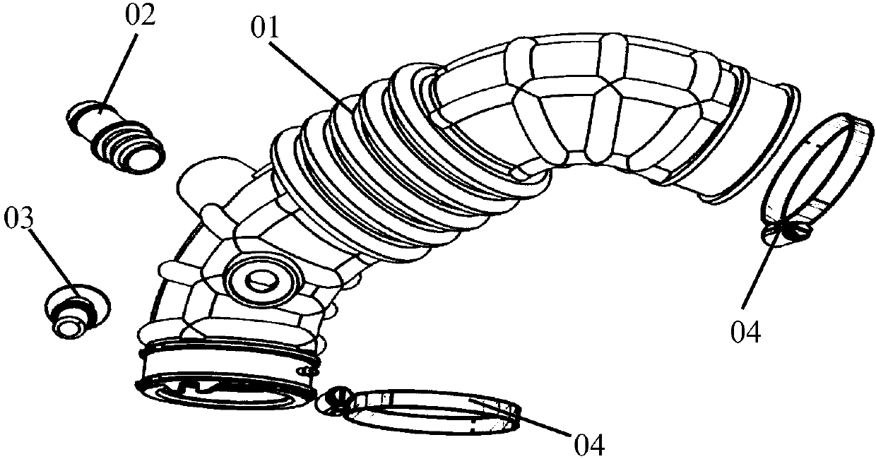
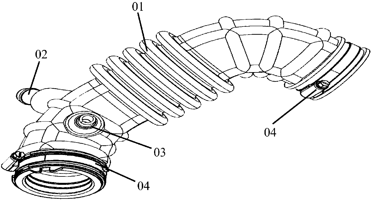
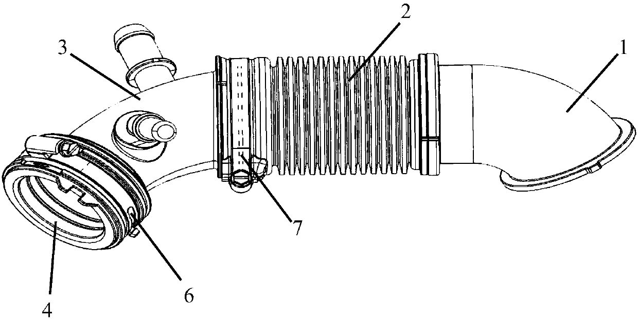
[0026] The following with attached Figure 3 to Figure 8 An air filter air outlet pipe of the present invention will be further described in detail.

[0027] An air filter outlet pipe of the present invention, please refer to Figure 3 to Figure 8Relevant figures include the first air filter outlet pipe 1, the third air filter outlet pipe 3, the rubber sleeve 4 and the second air filter outlet pipe 2 made of elastomer material, the second air filter outlet pipe 2 The upper ring is provided with at least three corrugations, the left end of the first air filter outlet pipe 1 is fixedly connected to the right end of the second air filter outlet pipe 2, and the left end of the second air filter outlet pipe 2 is connected to the first air filter outlet pipe. The right end of the third air filter outlet pipe 3 is detachably fixedly connected, the left end of the third air filter outlet pipe 3 is releasably connected to the right end of the rubber sleeve 4, and the first air filter ...


PUM


Abstract

The invention discloses an air filter air outlet pipe. The air filter air outlet pipe comprises a first air filter air outlet pipe, a third air filter air outlet pipe, a rubber sleeve and a second airfilter air outlet pipe made of an elastomer material, at least three circles of ripples are annularly arranged on the second air filter air outlet pipe, and the left end part of the first air filterair outlet pipe is fixedly connected with the right end part of the second air filter air outlet pipe. The left end part of the second air filter air outlet pipe is detachably and fixedly connected with the right end part of the third air filter air outlet pipe, the left end of the third air filter air outlet pipe is detachably connected with the right end of the rubber sleeve in an inserted mode,the right end of the first air filter air outlet pipe is fixedly connected with the air filter upper shell, and the left end of the rubber sleeve is detachably and fixedly connected with an engine connector in a sealed mode. According to the air filter air outlet pipe, the usage amount of the rubber hose is reduced, the part cost is reduced, the sealing performance is improved, the arrangement space is small, the interference between the air filter air outlet pipe and the peripheral parts is avoided, the abrasion risks are eliminated, the manufacturing process is simple, the manufacturing errors are reduced, and the vibration isolation performance is improved.

Description

technical field [0001] The invention relates to an air filter outlet pipe of an automobile, in particular to an air filter outlet pipe of a supercharged engine. Background technique [0002] One of the main functions of the air filter exhaust pipe assembly is to isolate the vibration generated when the engine is working. In the intake system of a turbocharged engine, when the turbocharger is working, its surface temperature can reach up to 150°C, which requires the air filter outlet pipe connected to the turbocharger to be able to work normally at a high temperature of 150°C. Work. Under such high temperature conditions, AEM or FKM rubber is usually selected for the air filter outlet pipe to ensure good sealing and vibration isolation under high temperature conditions. [0003] At present, the air filter exhaust pipe assembly (such as figure 1 and as figure 2 As shown), it mainly includes the air filter outlet pipe 01, the pressure relief pipe joint 02, the PCV pipe joi...

Claims


Application Information

Patent Timeline
Patent Type & Authority Applications(China)
IPC IPC(8): F02M35/104
CPCF02M35/104F02M35/10137F02M35/10321F02M35/10006F02M35/10091F02M35/10157
Inventor 罗宏锦李锐黄建忠施昭林覃小金
Owner SAIC-GM-WULING AUTOMOBILE CO LTD
Why Eureka
Try Eureka