Control system and method based on residual steam and residual heat recovery device

A technology of waste heat recovery device and waste heat recovery system, which is applied in the control of water supply, preheating, steam generation, etc., can solve the problems of monitoring and dredging of the discharge process, and it is difficult to ensure the utilization of heat energy, and achieves the effect of ensuring safety and reliability.

Pending Publication Date: 2019-12-03
常州绿资环保设备有限公司
View PDF0 Cites 2 Cited by
  • Summary
  • Abstract
  • Description
  • Claims
  • Application Information

AI Technical Summary

Problems solved by technology

The direct discharge of excess steam is a waste of heat energy in steam. Although there are methods for steam recycling in the prior art, they are still based on regular discharge, and the entire discharge process is not monitored and guided. It is difficult to ensure the circulation process. Maximization of thermal energy utilization

Method used


Image

  • Control system and method based on residual steam and residual heat recovery device
  • Control system and method based on residual steam and residual heat recovery device
  • Control system and method based on residual steam and residual heat recovery device

Examples


Embodiment 1

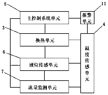
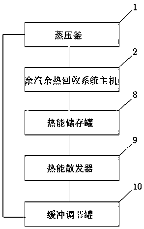
[0024] A control system based on a steam and heat recovery device, including an autoclave 1 and a steam and heat recovery system host 2, and also includes a heat exchange unit 3, a temperature sensing unit 4, a main control system unit 5, and a liquid level sensing unit 6 and a flow monitoring unit 7; the heat exchange unit 3 is set in the main unit 2 of the waste steam and heat recovery system, the main unit 2 of the waste steam and heat recovery system is connected to the thermal energy storage tank 8, and the liquid level transmitter The sensing unit 6 and the flow monitoring unit 7 are arranged in the thermal energy storage tank 8 ; the thermal energy storage tank 8 is connected to a thermal energy distributor 9 , and the thermal energy distributor 9 is connected to a buffer regulating tank 10 .

[0025] The temperature sensing unit 4 is also arranged on the main unit 2 of the steam and heat recovery system, the heat radiator 9 and the buffer regulating tank 10 . The main ...

Embodiment 2

[0028] The main control system unit 5 presets the start-up temperature value of the power delivery pump, and obtains the temperature parameter transmitted by the thermocouple in the main engine; when the main control system unit 5 detects that the temperature of the medium in the main engine has reached the output temperature, the medium will be delivered Enter the thermal energy storage tank 8, and obtain the liquid level information in the thermal energy storage tank 8; at the same time, monitor the real-time flow of the thermal energy storage tank 8 to the outside, and transport it to each production section according to the corresponding flow rate. When the liquid level in the thermal energy storage tank 8 reaches the set maximum value or minimum value, combined with the temperature sensing unit 4 to obtain the real-time temperature of the production line at this time, the output flow rate is controlled to avoid danger caused by excessive temperature of one of the devices ....


PUM


Abstract

The invention discloses a control system based on a residual steam and residual heat recovery device, which comprises a still kettle, a residual steam and residual heat recovery system host, a heat exchange unit, a temperature sensing unit, a main control system unit, a liquid level sensing unit and a flow monitoring unit, wherein the heat exchange unit is arranged in the residual steam and residual heat recovery system host, the residual steam and residual heat recovery system host is connected with a heat energy storage tank, and the liquid level sensing unit and the flow monitoring unit arearranged in the heat energy storage tank; the heat energy storage tank is connected with a heat energy radiator, and the heat energy radiator is connected with a buffer adjusting tank; according to the invention, different parameter data when the medium is conveyed to each stage are obtained through each monitoring unit, so that no heat loss of the medium is ensured in the transmission process, and resource utilization maximization is achieved.

Description

technical field [0001] The invention relates to the field of building material production lines, in particular to a control system and method based on a waste steam waste heat recovery device. Background technique [0002] The building material production line is generally aerated concrete block production line, autoclaved brick production line, prefabricated pipe pile production line, etc. After the traditional production line produces finished products, it is necessary to discharge the excess steam in the autoclave where the finished products are placed. The direct discharge of excess steam is a waste of heat energy in steam. Although there are methods for steam recycling in the prior art, they are still mostly based on timed discharge, without monitoring and guiding the entire discharge process, and it is difficult to ensure the circulation process. Maximization of thermal energy utilization. Contents of the invention [0003] In order to solve the above problems and e...

Claims


Application Information

Patent Timeline
Patent Type & Authority Applications(China)
IPC IPC(8): F22D1/32F22D3/00F22D5/00F22D7/12
CPCF22D1/32F22D3/00F22D5/00F22D7/12
Inventor 金钟
Owner 常州绿资环保设备有限公司
Why Eureka
Try Eureka