Light source device and projection display apparatus
一种光源装置、光源单元的技术,应用在放映装置、光学、摄影等方向,能够解决光合成部大型化、散热器冷却性能降低、光源破损等问题,达到高亮度化小型化的效果
- Summary
- Abstract
- Description
- Claims
- Application Information
AI Technical Summary
Problems solved by technology
Method used
Image
Examples
Embodiment approach 1
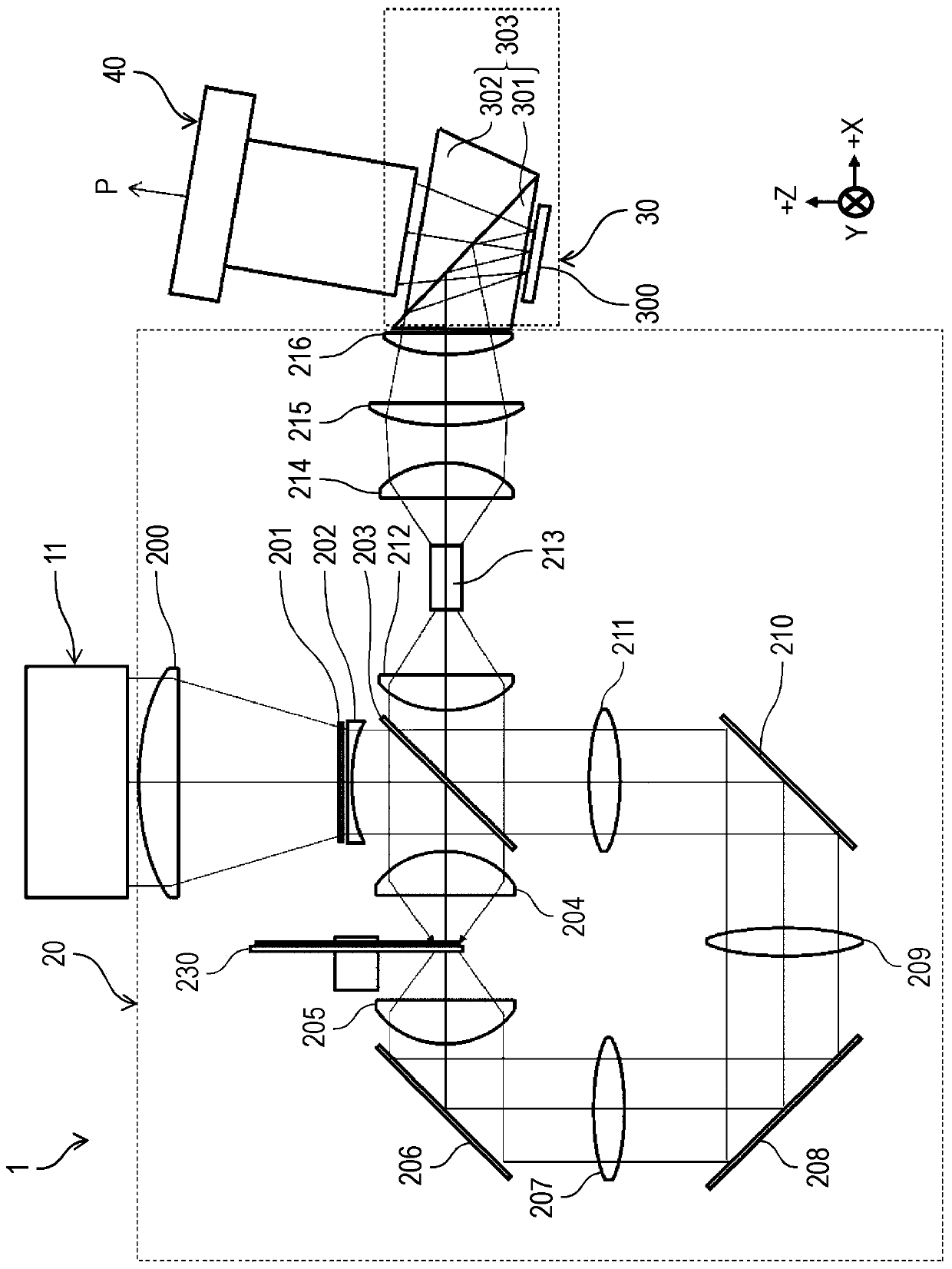
[0071] Below, use Figure 1 to Figure 6 , Embodiment 1 will be described. Hereinafter, a projector will be described as a specific embodiment of the projection-type image display device according to the present disclosure.
[0072] [1-1. Structure]
[0073] [1-1-1. Structure of Projector]
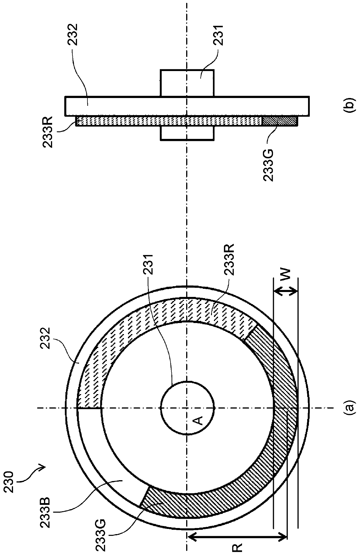
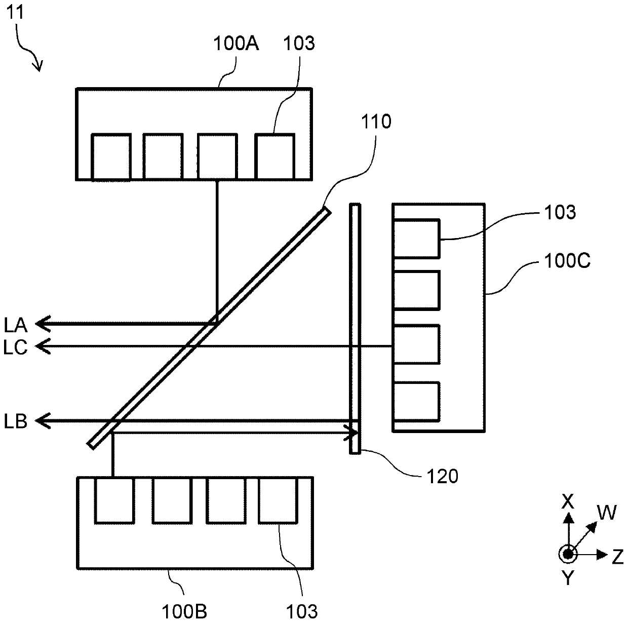
[0074] figure 1 It is a figure showing the structure of the projector concerning Embodiment 1. The projector 1 includes a light source device 11 , an illumination optical system 20 , an image generation unit 30 , and a projection optical system 40 . In addition, in figure 1 The XYZ orthogonal coordinate system is shown in the figure 2 The same XYZ rectangular coordinate system is appropriately shown in the subsequent drawings as well.
[0075] The projector 1 guides the light emitted from the light source device 11 to the image generation unit 30 through the illumination optical system 20, and uses a digital micromirror device (Digital Micromirror Device) (hereinafter, referred to a...
Embodiment approach 2
[0100] Below, use Figure 7 ~ Figure 9 Embodiment 2 will be described. In Embodiment 2, the same reference numerals are assigned to the same components as in Embodiment 1, and repeated description thereof will be omitted.
[0101] exist Figure 7 The configuration of the light source device 12 according to Embodiment 2 is shown in . In the light source device 12 , the first light source unit 100A and the second light source unit 100B are disposed facing the X direction with the polarizing beam splitter 110 interposed therebetween. The arrangement is shifted by half the pitch between the light source elements. In addition, the phase difference plate 130 is disposed near the emission port of the light source device 12 .
[0102] exist Figure 8 The structure of the phase difference plate 130 is shown in . Figure 8 (a) is the main view, Figure 8 (b) is a side view. The retardation film 130 has an opening area 131 (an area to which a grid is applied) and a non-opening ar...
Embodiment approach 3
[0106] Below, use Figure 10 ~ Figure 12 Embodiment 3 will be described. exist Figure 10 The configuration of the light source device 13 according to Embodiment 3 is shown in . The light source device 13 is composed of a first light source unit 100A, a second light source unit 100B, a third light source unit 100C, a fourth light source unit 100D, a first polarizing beam splitter 110A, a second polarizing beam splitter 110B, collimating lenses 140, 150 and a polarization conversion element 160.
[0107] The respective structures of the first light source unit 100A to the fourth light source unit 100D and Figure 4 The light source unit 100 shown is the same. The first light source unit 100A and the second light source unit 100B are arranged to face each other with the first polarizing beam splitter 110A disposed therebetween so that the optical axes in the X direction of the emitted light from each light source element are aligned, and the third The light source unit 100C...
PUM
 Abstract
Description
Claims
Application Information
 - R&D
- Intellectual Property
- Life Sciences
- Materials
- Tech Scout
- Unparalleled Data Quality
- Higher Quality Content
- 60% Fewer Hallucinations
Browse by: Latest US Patents, China's latest patents, Technical Efficacy Thesaurus, Application Domain, Technology Topic, Popular Technical Reports.
© 2025 PatSnap. All rights reserved.Legal|Privacy policy|Modern Slavery Act Transparency Statement|Sitemap|About US| Contact US: help@patsnap.com


