Miniaturized ultrahigh frequency antenna based on split-ring resonator loading

A split resonant ring, UHF technology, applied in the direction of antenna, antenna grounding device, antenna grounding switch structure connection, etc., can solve the problems of high antenna cost, high profile, large volume of satellite communication antenna, etc., to meet the requirements of miniaturization applications , Small size design, low cost effect

Inactive Publication Date: 2019-12-03
SOUTH CHINA UNIV OF TECH
View PDF5 Cites 7 Cited by
  • Summary
  • Abstract
  • Description
  • Claims
  • Application Information

AI Technical Summary

Problems solved by technology

[0006] 1. Traditional satellite communication antennas in the UHF band are large in size and high in profile, which cannot meet the technical requirements of miniaturization and low profile of modern satellite communications
[0007] 2. The binary sequence feed antenna cannot produce a rotationally symmetrical radiation pattern, the three-element sequence feed antenna cannot realize multi-band applications, and the four-element sequence feed antenna has a complex feeding network and high antenna cost
[0008] 3. The existing antenna miniaturization technology mainly relies on meandering technology and medium loading, while meandering technology has a limited degree of miniaturization, and medium loading has too much influence on the radiation performance of the antenna

Method used


Image

  • Miniaturized ultrahigh frequency antenna based on split-ring resonator loading
  • Miniaturized ultrahigh frequency antenna based on split-ring resonator loading
  • Miniaturized ultrahigh frequency antenna based on split-ring resonator loading

Examples


Embodiment

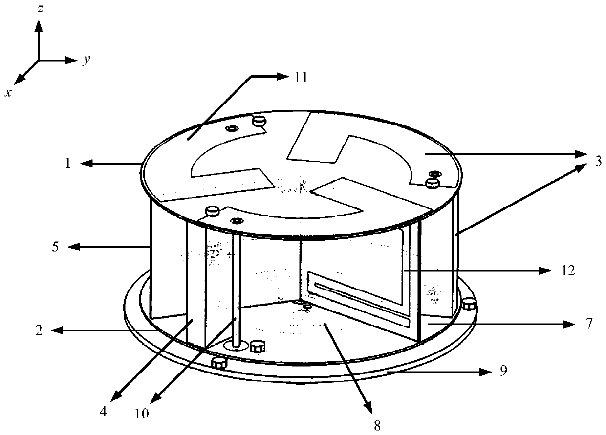
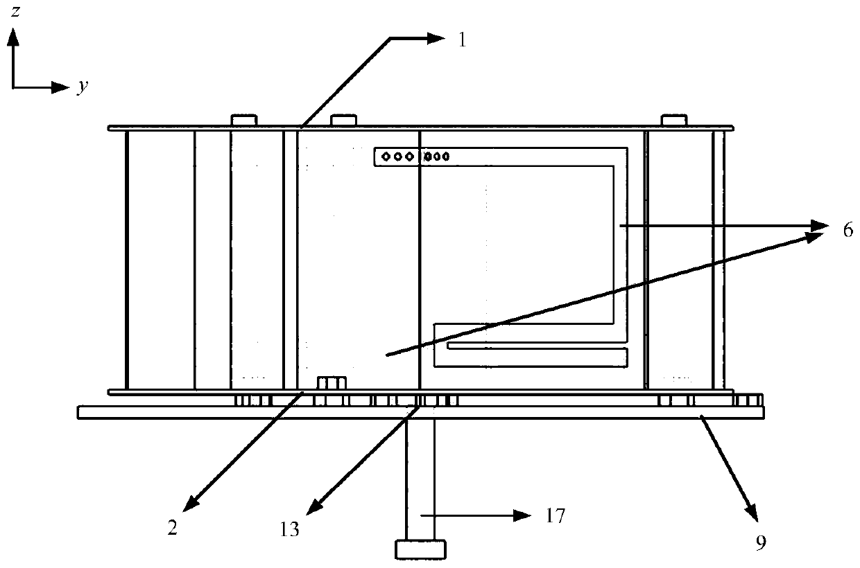
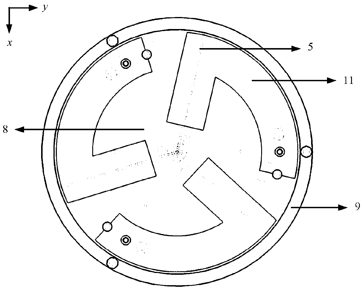
[0062] Such as Figure 1 to Figure 5 As shown, a miniaturized UHF antenna based on split resonator ring loading, the antenna includes:

[0063] The upper substrate 1 is arranged on the top of the miniaturized UHF antenna;

[0064] The lower substrate 2 is arranged in parallel directly below the upper substrate 1;

[0065] Three antenna units 3 are arranged between the upper substrate 1 and the lower substrate 2, and are distributed rotationally symmetrically around the central axis of the overall structure of the antenna, for transmitting UHF signals;

[0066] At least three vertical substrates 5 are vertically arranged between the upper substrate 1 and the lower substrate 2, and are distributed rotationally symmetrically around the central axis of the overall structure of the antenna;

[0067] The split resonant rings 6 are respectively printed on the largest surface of each of the vertical substrates 5, and the split resonant rings 6 on adjacent vertical substrates 5 are e...


PUM


Abstract

The invention discloses a miniaturized ultrahigh frequency antenna based on split-ring resonator loading, which comprises an upper-layer substrate, a lower-layer substrate, three antenna units, at least three vertical substrates, split-ring resonators, a metal floor plate, a feed network and three feed probes, wherein the three antenna units are rotationally and symmetrically arranged between theupper-layer substrate and the lower-layer substrate; the at least three vertical substrates are rotationally, symmetrically and vertically arranged between the upper-layer substrate and the lower-layer substrate; the split-ring resonators are printed on the maximum surfaces of the vertical substrates respectively, and the split-ring resonators on the adjacent vertical substrates are electrically connected; the metal floor plate is printed on the upper surface of the lower-layer substrate; the feed network is printed on the lower surface of the lower-layer substrate and is used for receiving the ultrahigh-frequency signals and generating three paths of sequence feed signals with the same amplitude and the phase difference of 120 degrees in sequence; and the three feed probes are arranged between the upper-layer substrate and the lower-layer substrate and are used for respectively feeding the three paths of sequence feed signals to the three antenna units. The antenna has the advantagesof being small in size, low in cost, convenient to assemble and the like, and miniaturization, good electrical characteristics and dual-band application in the field of satellite communication can bemet.

Description

technical field [0001] The present invention relates to the technical field of antennas, in particular to a ground satellite receiving antenna, in particular to a miniaturized ultra-high frequency (UHF) triple-sequence-fed dual-frequency antenna based on split resonant ring (SRR) loading. Background technique [0002] The application of satellite communication technology is mainly reflected in two aspects of military use and civilian use (industrial and agricultural production). The rapid development of wireless communication technology also makes the field of satellite communication technology develop rapidly. Satellite communication receiving and transmitting signals mainly rely on antennas, and the size of antennas is mainly determined by the operating frequency. Therefore, traditional UHF satellite communication antennas are generally large in size and high in profile, which is difficult to meet the needs of modern satellite communication. [1] proposed a three-element se...

Claims


Application Information

Patent Timeline
Patent Type & Authority Applications(China)
IPC IPC(8): H01Q1/36H01Q1/48H01Q1/50H01Q5/20H01Q5/10
CPCH01Q1/36H01Q1/48H01Q1/50H01Q5/10H01Q5/20
Inventor 孙远发廖绍伟薛泉
Owner SOUTH CHINA UNIV OF TECH
Why Eureka
Try Eureka