DC controllable lightning arrester device

A lightning arrester and device technology, which is applied in the field of DC controllable arrester devices, can solve problems such as system overvoltage, short-circuit ratio reduction, and reliability reduction, and achieve the effects of reducing the number of series modules, reducing the level of overvoltage, and fast action speed

Pending Publication Date: 2019-12-03
GLOBAL ENERGY INTERCONNECTION RES INST CO LTD +2
View PDF0 Cites 6 Cited by
  • Summary
  • Abstract
  • Description
  • Claims
  • Application Information

AI Technical Summary

Problems solved by technology

[0002] With the continuous improvement of DC transmission capacity, the characteristics of "strong DC and weak AC" appear, which will lead to a decrease in the short-circuit ratio, and the electrical distance between the inverter stations is relatively close. The failure of the AC system near the converter station may cause multiple DC circuits to occur at the same time Commutation failure affects the safe and stable operation of AC and DC systems
If the commutation on the inverter side fails, the power on the rectifier side cannot be sent normally, and the energy at the receiving end cannot be consumed normally, which will lead to system overvoltage
[0003] In the existing technology, the ZnO arrester is an ideal technical means to suppress overvoltage because of its good nonline

Method used


Image

  • DC controllable lightning arrester device
  • DC controllable lightning arrester device
  • DC controllable lightning arrester device

Examples


Example Embodiment

[0020] The technical solutions of the present invention will be clearly and completely described below in conjunction with the accompanying drawings. Obviously, the described embodiments are part of the embodiments of the present invention, rather than all of them. Based on the embodiments of the present invention, all other embodiments obtained by those of ordinary skill in the art without creative work shall fall within the protection scope of the present invention.

[0021] In the description of the present invention, it should be noted that the terms "installation", "connected" and "connected" should be understood in a broad sense, unless otherwise clearly specified and limited. For example, they can be fixed or detachable. Connected or integrally connected; it can be a mechanical connection or an electrical connection; it can be directly connected, or indirectly connected through an intermediate medium, or it can be the internal connection of the two components, which can be ...


PUM


Abstract

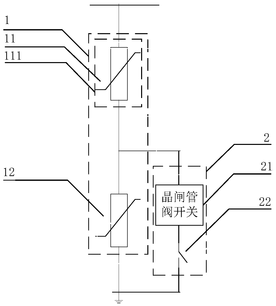
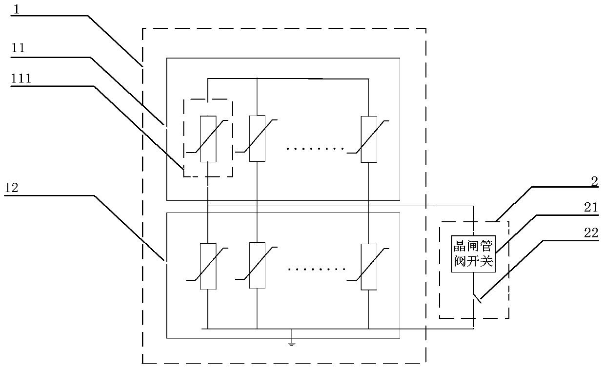
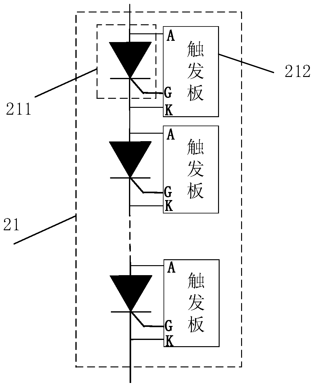
The invention provides a DC controllable lightning arrester device. The DC controllable lightning arrester device comprises a lightning arrester body and a hybrid switch, wherein the lightning arrester body comprises a lightning arrester fixed part and a lightning arrester controllable part, the lightning arrester fixed part and the lightning arrester controllable part respectively comprise at least one column of lightning arrester units, one end of a parallel circuit formed by the lightning arrester controllable part and the hybrid switch is grounded, the other end is connected with the lightning arrester fixed part, the hybrid switch comprises a thyristor valve switch and a mechanical switch which are connected in series, and the hybrid switch is connected with two ends of the lightningarrester controllable part in parallel. The DC controllable lightning arrester device is advantaged in that the thyristor valve switch and the mechanical switch are utilized to form the high voltage DC hybrid switch type controllable lightning arrester, the thyristor switch is ensured to be reliably turned off, so the lightning arrester returns to normal operation, the lightning arrester body achieves dual functions of energy release and overvoltage suppression, a charge rate of the whole lightning arrester under the operation voltage is reduced, the safety margin of the lightning arrester isimproved, and reliability of the lightning arrester is enhanced.

Description

technical field [0001] The invention relates to the field of electrical equipment in a power system, in particular to a DC controllable lightning arrester device. Background technique [0002] With the continuous improvement of DC transmission capacity, the characteristics of "strong DC and weak AC" appear, which will lead to a decrease in the short-circuit ratio, and the electrical distance between the inverter stations is relatively close. The failure of the AC system near the converter station may cause multiple DC circuits to occur at the same time The commutation failure affects the safe and stable operation of the AC and DC system. If the phase commutation on the inverter side fails, the power on the rectifier side cannot be sent normally, and the energy at the receiving end cannot be consumed normally, which will lead to system overvoltage. [0003] In the existing technology, the ZnO arrester is an ideal technical means to suppress overvoltage because of its good no...

Claims


Application Information

Patent Timeline
IPC IPC(8): H02H9/04H02J3/36
CPCH02H9/048H02J3/36Y02E60/60
Inventor 乔光尧李芳义曾洪涛赵国亮邓占锋靳艳娇李卫国苏铁山
Owner GLOBAL ENERGY INTERCONNECTION RES INST CO LTD
Why Eureka
Try Eureka