Control method of rotating motor

A technology for rotating electrical machines and control methods, which is applied in the direction of motor control, control systems, electrical components, etc., and can solve the problems of connecting device wear, reducing device service life, damage, etc., and achieve the effect of controlling safety and avoiding negative effects

Active Publication Date: 2019-12-03
BEIJING NAURA MICROELECTRONICS EQUIP CO LTD
View PDF7 Cites 1 Cited by
  • Summary
  • Abstract
  • Description
  • Claims
  • Application Information

AI Technical Summary

Problems solved by technology

[0008] 1. The rotation control part of the rotating motor adopts open-loop control, which is only responsible for issuing commands, and does not guarantee the execution results of the commands, including the success of the speed setting of the rotating motor after sending the speed in the speed setting step. Return to the origin step After the command is issued, it cannot be guaranteed that the rotating motor will eventually stay at the origin position;
[0009] 2. In the emergency stop step, if the current speed is high, the inertia will cause wear to the connecting device, reduce the service life of the device, and even cause the tray to directly deviate from the fixed position, causing greater damage;
[0010] 3. During the execution of the process menu, the rotating motor may cause an emergency stop due to an abnormality of the machine or itself, but the process will continue, the actual rotating motor does not rotate, and there is no alarm to remind the user, resulting in the wafer involved in subsequent work becoming waste directly affect the normal use of the machine, process debugging and normal mass production of the machine

Method used


Image

  • Control method of rotating motor
  • Control method of rotating motor
  • Control method of rotating motor

Examples


Embodiment Construction

[0052] The present invention will be described in more detail below with reference to the accompanying drawings. Although preferred embodiments of the invention are shown in the drawings, it should be understood that the invention may be embodied in various forms and should not be limited to the embodiments set forth herein. Rather, these embodiments are provided so that this disclosure will be thorough and complete, and will fully convey the scope of the disclosure to those skilled in the art.

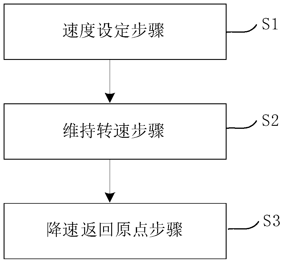
[0053] figure 2 A flowchart showing a control method of a rotating electric machine according to an exemplary embodiment of the present invention. Such as figure 2 As shown, the control of the rotating electrical machine mainly includes steps S1, S2, and S3.

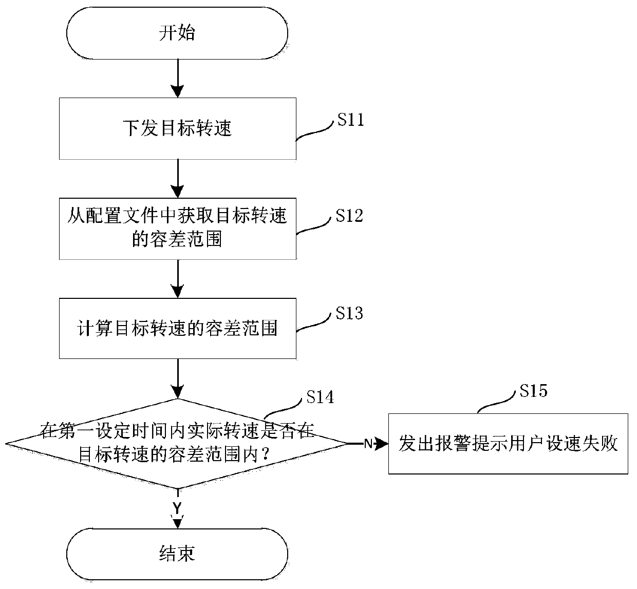
[0054] Step S1 is a speed setting step, which is used to set the target rotational speed before executing the process menu, and judge whether the speed setting is successful by obtaining the rotational speed fed back by the...


PUM


Abstract

The invention discloses a control method of a rotating motor, which is used for controlling the rotating motor in a machine table rotating device of semiconductor equipment. The control method of a rotating motor comprises the following steps of: a speed setting step of setting a target rotating speed before executing a process menu, and determining whether the speed setting is successful or not by acquiring the rotating speed fed back by the rotating motor in real time; a rotating speed maintaining step for maintaining the rotating speed of the rotating motor in the process of executing the process menu; and a step of reducing the speed and returning to the original point, namely reducing the speed of the rotating motor and returning to the original point after the process menu is executed, and determining whether the rotating motor returns to the original point successfully by acquiring the state fed back by the rotating motor in real time and detecting whether the rotating motor islocated at the original point position or not. In the speed setting step before the process menu is started and the speed reduction original point returning step after the process menu is ended, closed-loop control is adopted for the rotating motor, it is ensured that a control command of the rotating motor is successfully executed, and control over the rotating motor is safer, more reliable and more stable.

Description

technical field [0001] The invention relates to the field of semiconductor equipment, in particular to a control method for a rotating electrical machine. Background technique [0002] Semiconductor equipment for silicon epitaxy generally includes a process chamber 1, a heating device 2, a tray 3, an exhaust device 4, an air intake device 5, and a rotary lifting device 6, specifically as figure 1 shown. Among them, the rotating lifting device 6 drives the tray 3 to rotate and lift, cooperates with the manipulator to pick and place the sheet, and realizes that the tray 3 maintains a certain rotation during the process, which has an important impact on the process performance and is an important part of the semiconductor equipment. [0003] The rotary lifting device 6 usually includes a rotary motor and a lifting cylinder structure. For stable process performance, it is necessary to maintain the rotating motor at a stable speed and the lifting structure at a stable height du...

Claims


Application Information

Patent Timeline
Patent Type & Authority Applications(China)
IPC IPC(8): H02P29/10
CPCH02P29/10
Inventor 杜青
Owner BEIJING NAURA MICROELECTRONICS EQUIP CO LTD
Why Eureka
Try Eureka