Process for generating higher vpsa product pressure
A pressure and pressure swing adsorption technology, applied in other chemical processes, separation methods, dispersed particle separation, etc., can solve problems affecting product recovery rate, short cycle, etc., and achieve the effect of saving capital and operating costs
- Summary
- Abstract
- Description
- Claims
- Application Information
AI Technical Summary
Problems solved by technology
Method used
Image


Examples
Embodiment 1
[0080] The results are modeled and in N 2 The MTC is about 14 / s for low-rate devices and N 2 The MTC is about 26 / s obtained on high rate devices. Table 2 shows the modeled and demonstrated effects of not opening the product valve before 0.25s before the inflection point of the bed top and surge tank. This prevents the device from producing target purities for low-rate materials, and results in results that are economically comparable to high-rate materials (more material is required, but power consumption is reduced).
[0081] Table 2 .
[0082] with PPS Does not have PP High rate with PP High rate without PP purity 90.5% 88.6% 89.8% 89.9% Power(kW) 100.0% 97.7% 100.0% 97.2% Purity Correction Factor 101% 98% 100.0% 100% Purity Corrected Production 100.0% 100.0% 100.0% 98.1% Equipment Actual Purity 91.0% * 91.0% 90.5% Equipment actual production 100.0% * 100.0% 100.0% The actual power of the equipm...
Embodiment 2
[0086] By modeling and in N 2 The result is obtained on a high-efficiency device with an MTC of about 28 / s. Table 3 shows the modeling and demonstration effects of not fully opening the product valve until 2 s after the inflection point of the bed top and surge tank. This enables high-efficiency equipment to produce more O of the same purity 2 products, but has no effect on low-efficiency devices.
[0087] table 3
[0088] High speed without slowdown slow high speed purity 90.4% 90.5% Power(kW) 100.0% 99.6% Purity Correction Factor 101% 101% Purity Corrected Production 100.0% 101.1% Equipment Actual Purity 90.1% 91.0% Equipment actual production 100.0% 100.0% The actual power of the equipment 100.0% 100.4%
[0089]It should be understood that the foregoing description is only illustrative of the invention. Various alternatives and modifications can be devised by those skilled in the art without departing ...
Embodiment 3
[0091] For low rate equipment, where economically relevant, start with a maximum maximum pressure of 11.3 psig. In this case, ASME has a limit of 12 psig and provides a 0.5 psig offset for the process safety valve. This also takes into account a 0.2 psig normal variation in peak pressure cycle-to-cycle as part of the necessary assumptions for supply pressure. Table 4 shows typical pressure drop curves.
[0092] Table 4
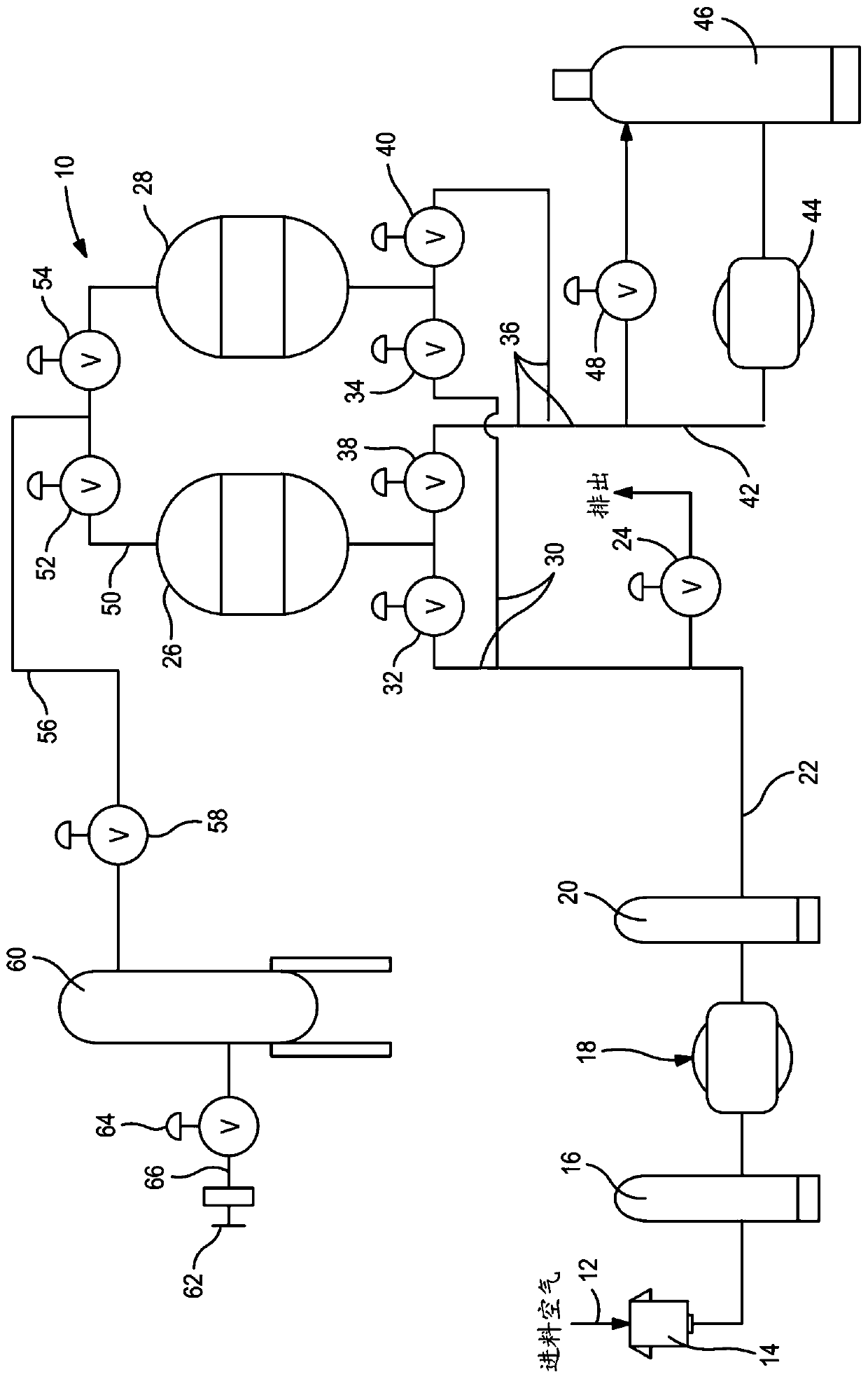
[0093] system components figure 1 and Figure 4 Tag of pressure (psig) filter housing 14 0.2 after cooling 18 0.25 pipe to bed 22 0.05 Bed dP 26 2 piping to buffer tank 50、52、56、58 0.4 Buffer tank swing 60 3.2 flow control valve 64 1.5 flow meter 100 1 check valve 101 1 flow meter with backup 103 1 backup offset 104 0.5 piping to burner 105 3 burner pipe 106 10 Burner Metering 106 1 dP in the system 25.1 supply pressure upper limit...
PUM
| Property | Measurement | Unit |
|---|---|---|
| The average particle size | aaaaa | aaaaa |
| Size | aaaaa | aaaaa |
| Size | aaaaa | aaaaa |
Abstract
Description
Claims
Application Information
 - R&D
- Intellectual Property
- Life Sciences
- Materials
- Tech Scout
- Unparalleled Data Quality
- Higher Quality Content
- 60% Fewer Hallucinations
Browse by: Latest US Patents, China's latest patents, Technical Efficacy Thesaurus, Application Domain, Technology Topic, Popular Technical Reports.
© 2025 PatSnap. All rights reserved.Legal|Privacy policy|Modern Slavery Act Transparency Statement|Sitemap|About US| Contact US: help@patsnap.com